
Arduino Mega 2560 and Raspberry Pi 5 Controlled Interface with OLED Display, Buzzer, and Keypad
View and Edit Project In Cirkit Designer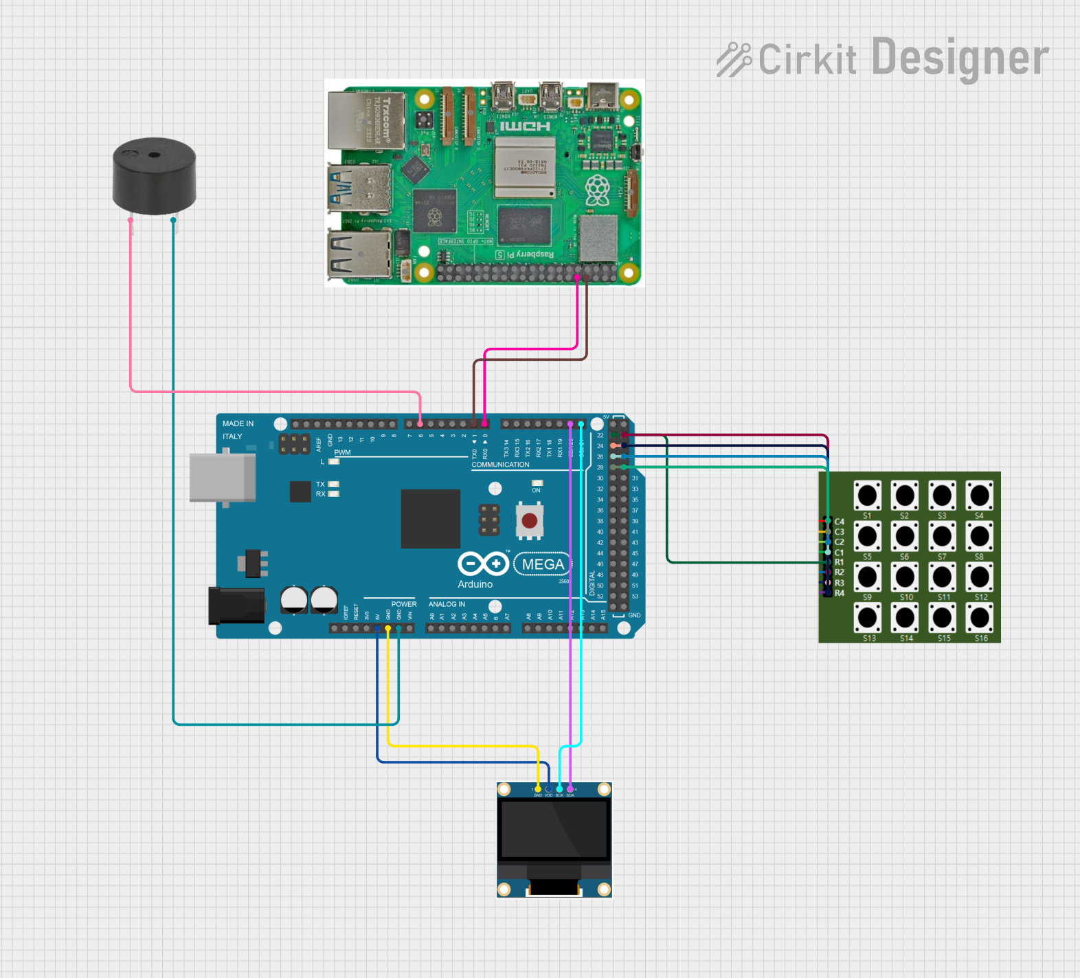
Circuit Documentation
Summary of the Circuit
This circuit integrates an Arduino Mega 2560 with a Raspberry Pi 5, a 0.96" OLED display, a buzzer, and a 4×4 keypad. The Arduino Mega 2560 serves as the primary microcontroller, interfacing with the OLED display for visual output, the buzzer for audio signaling, and the keypad for user input. The Raspberry Pi 5 is connected to the Arduino Mega 2560 via GPIO pins, allowing for communication between the two devices. The circuit is designed to leverage the capabilities of both the Arduino and Raspberry Pi platforms, with the Arduino handling real-time interactions and the Raspberry Pi providing higher-level processing and connectivity options.
Component List
Arduino Mega 2560
- Microcontroller board based on the ATmega2560
- Offers numerous digital and analog I/O pins
- Provides PWM output, I2C, SPI, and UART communication
Raspberry Pi 5
- A compact single-board computer with a powerful CPU and GPU
- Features a variety of connectivity options including USB, Ethernet, and GPIO
- Supports various operating systems and can run high-level applications
Buzzer
- An electromechanical component that produces sound
- Typically used for alarms, notifications, or user feedback
4×4 Keypad
- An input device with 16 buttons arranged in a 4x4 matrix
- Allows for user input through multiple keypress combinations
0.96" OLED
- A small display screen that uses organic light-emitting diodes
- Provides a high-contrast visual output for displaying text or graphics
Wiring Details
0.96" OLED
- VDD connected to Arduino Mega 2560 5V
- GND connected to Arduino Mega 2560 GND
- SCK connected to Arduino Mega 2560 D21/SCL
- SDA connected to Arduino Mega 2560 D20/SDA
Buzzer
- PIN connected to Arduino Mega 2560 D6 PWM
- GND connected to Arduino Mega 2560 GND
4×4 Keypad
- C3 connected to Arduino Mega 2560 D28
- C1 connected to Arduino Mega 2560 D26
- R3 connected to Arduino Mega 2560 D24
- R1 connected to Arduino Mega 2560 D22
- C4 connected to Arduino Mega 2560 D29
- C2 connected to Arduino Mega 2560 D27
- R4 connected to Arduino Mega 2560 D25
- R2 connected to Arduino Mega 2560 D23
Raspberry Pi 5
- GPIO 15 connected to Arduino Mega 2560 D0 RX0
- GPIO 14 connected to Arduino Mega 2560 D1 TX0
Documented Code
Arduino Mega 2560 Code (sketch.ino)
void setup() {
  // put your setup code here, to run once:

}

void loop() {
  // put your main code here, to run repeatedly:

}
Additional Notes
- The provided code for the Arduino Mega 2560 is a template with empty setup and loop functions. Actual implementation details should be added based on the specific requirements of the circuit's application.
- The Raspberry Pi 5 code is not provided in the input and would typically be written in a high-level language such as Python or C++ and run under an operating system like Raspberry Pi OS.
- The buzzer and keypad are controlled via the specified digital pins on the Arduino Mega 2560, and the OLED display communicates over the I2C interface.
- The connection between the Raspberry Pi 5 and the Arduino Mega 2560 allows for serial communication, enabling the two devices to exchange data.