
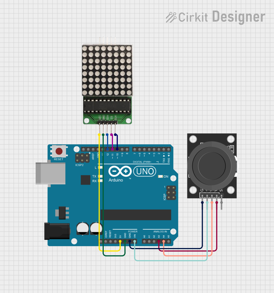
Circuit Documentation
Summary
This circuit consists of an Arduino UNO microcontroller, an LED Matrix, and a KY-023 Dual Axis Joystick Module. The Arduino UNO serves as the central controller, interfacing with the LED Matrix to display information and the joystick module to receive user input.
Component List
Arduino UNO
- Description: A microcontroller board based on the ATmega328P.
- Pins: UNUSED, IOREF, Reset, 3.3V, 5V, GND, Vin, A0, A1, A2, A3, A4, A5, SCL, SDA, AREF, D13, D12, D11, D10, D9, D8, D7, D6, D5, D4, D3, D2, D1, D0
LED Matrix
- Description: A display module used to show visual information.
- Pins: CLK, CS, DIN, GND, VCC
KY-023 Dual Axis Joystick Module
- Description: A joystick module used to capture user input in two axes.
- Pins: GND, +5V, VRx, VRy, SW
Wiring Details
Arduino UNO
- 5V: Connected to VCC of LED Matrix
- GND: Connected to GND of LED Matrix and GND of KY-023 Dual Axis Joystick Module
- Vin: Connected to +5V of KY-023 Dual Axis Joystick Module
- A3: Connected to VRy of KY-023 Dual Axis Joystick Module
- A4: Connected to VRx of KY-023 Dual Axis Joystick Module
- D12: Connected to DIN of LED Matrix
- D11: Connected to CS of LED Matrix
- D10: Connected to CLK of LED Matrix
LED Matrix
- VCC: Connected to 5V of Arduino UNO
- GND: Connected to GND of Arduino UNO
- DIN: Connected to D12 of Arduino UNO
- CS: Connected to D11 of Arduino UNO
- CLK: Connected to D10 of Arduino UNO
KY-023 Dual Axis Joystick Module
- GND: Connected to GND of Arduino UNO
- +5V: Connected to Vin of Arduino UNO
- VRy: Connected to A3 of Arduino UNO
- VRx: Connected to A4 of Arduino UNO
Code Documentation
Arduino UNO Code
sketch.ino
void setup() {
  // put your setup code here, to run once:

}

void loop() {
  // put your main code here, to run repeatedly:

}
documentation.txt
This document provides a comprehensive overview of the circuit, including a summary, detailed component list, wiring details, and documented code.