
Circuit Documentation
Summary of the Circuit
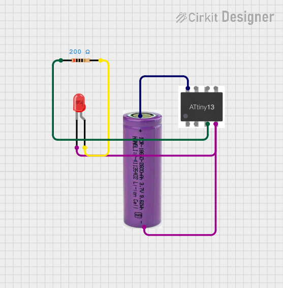
This circuit is designed to control an LED using an ATtiny microcontroller. The LED is turned on by the microcontroller via one of its GPIO pins. A resistor is included in series with the LED to limit the current and protect the LED from damage. The circuit is powered by a 3.3V battery, which also supplies power to the ATtiny microcontroller.
Component List
ATtiny Microcontroller
- Description: A small, low-power microcontroller suitable for simple tasks and battery-powered applications.
- Pins: PB5, PB3, PB4, GND, PB0, PB1, PB2, VCC
Resistor
- Description: A passive two-terminal electrical component that implements electrical resistance as a circuit element.
- Resistance: 200 Ohms
LED: Two Pin (red)
- Description: A basic red light-emitting diode for indicating power or status.
- Pins: cathode, anode
3.3V Battery
- Description: A power source for the circuit, providing a constant voltage of 3.3V.
- Pins: + (positive), - (negative)
Wiring Details
ATtiny Microcontroller
- PB4: Connected to the Resistor (pin1)
- GND: Connected to the LED (cathode) and the 3.3V Battery (-)
- VCC: Connected to the 3.3V Battery (+)
Resistor
- pin1: Connected to the ATtiny Microcontroller (PB4)
- pin2: Connected to the LED (anode)
LED: Two Pin (red)
- cathode: Connected to the ATtiny Microcontroller (GND) and the 3.3V Battery (-)
- anode: Connected to the Resistor (pin2)
3.3V Battery
- +: Connected to the ATtiny Microcontroller (VCC)
- -: Connected to the ATtiny Microcontroller (GND) and the LED (cathode)
Documented Code
ATtiny Microcontroller Code
File: sketch.ino
/*
 * This Arduino Sketch is for an ATtiny microcontroller.
 * It turns on an LED connected to pin 4 (PB4) of the ATtiny.
 */

void setup() {
  // Initialize pin 4 (PB4) as an output
  pinMode(3, OUTPUT);
  // Turn on the LED connected to pin 4
  digitalWrite(3, HIGH);
}

void loop() {
  // No repeated actions needed
}
This code configures pin PB4 (referred to as pin 3 in the Arduino environment) of the ATtiny microcontroller as an output and sets it to a high state, which turns on the connected LED. The loop() function is empty as no repeated action is required; the LED remains on as long as the microcontroller is powered.