Arduino and ESP32-Based Environmental Monitoring System with Wi-Fi Connectivity
Circuit Documentation
Summary
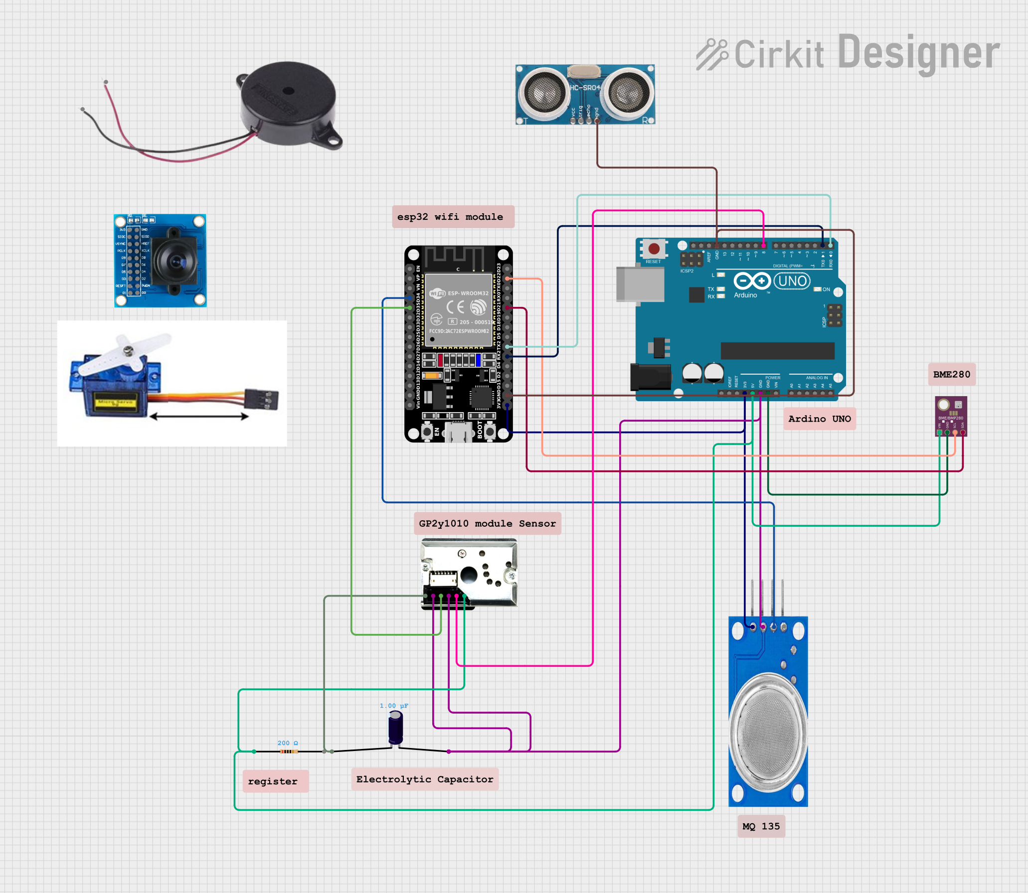
This circuit integrates an Arduino UNO, an ESP32, and various sensors and components to create a comprehensive system. The sensors include an MQ135 gas sensor, a BME/BMP280 environmental sensor, a GP2Y1010AU0F dust sensor, and an ultrasonic sensor. Additionally, a servo motor and a buzzer are included. The circuit is designed to monitor environmental conditions and control actuators based on sensor inputs.
Component List
Arduino UNO
- Description: A microcontroller board based on the ATmega328P.
- Pins: UNUSED, IOREF, Reset, 3.3V, 5V, GND, Vin, A0, A1, A2, A3, A4, A5, SCL, SDA, AREF, D13, D12, D11, D10, D9, D8, D7, D6, D5, D4, D3, D2, D1, D0
MQ135
- Description: Gas sensor for detecting air quality.
- Pins: VCC, GND, A0, D0
BME/BMP280
- Description: Environmental sensor for measuring temperature, humidity, and pressure.
- Pins: GND, SCL, SDA, VIN
GP2Y1010AU0F
- Description: Dust sensor for measuring particulate matter in the air.
- Pins: VCC, Vout, S-GND, LED, LED-GND, V-LED
Resistor
- Description: A 200 Ohm resistor.
- Pins: pin1, pin2
- Properties: Resistance: 200 Ohms
Electrolytic Capacitor
- Description: A capacitor with a capacitance of 1 µF.
- Pins: -, +
- Properties: Capacitance: 1 µF
ESP32 (30 pin)
- Description: A microcontroller with Wi-Fi and Bluetooth capabilities.
- Pins: EN, VP, VN, D34, D35, D32, D33, D25, D26, D27, D14, D12, D13, GND, Vin, D23, D22, TX0, RX0, D21, D19, D18, D5, TX2, RX2, D4, D2, D15, 3V3
Ultrasonic Sensor
- Description: Sensor for measuring distance using ultrasonic waves.
- Pins: +VCC, Trigger, Echo, GND
Servo Motor 9G
- Description: A small servo motor for precise control of angular position.
- Pins: VCC 5V, PMW, GND
OV7725
- Description: Camera module for capturing images.
- Pins: 3V3, GND, SIOC, SIOD, VSYNC, HREF, PCLK, XCLK, D9, D8, D7, D6, D5, D4, D3, D2, RESET, D1, D0, PWDN
Buzzer
- Description: An audio signaling device.
- Pins: POSITIVE, NEGATIVE
Wiring Details
Arduino UNO
- 3.3V connected to ESP32 (30 pin) 3V3 and MQ135 VCC
- 5V connected to GP2Y1010AU0F VCC, Resistor pin1, and BME/BMP280 VIN
- GND connected to GP2Y1010AU0F S-GND, GP2Y1010AU0F LED-GND, MQ135 GND, BME/BMP280 GND, ESP32 (30 pin) GND, Ultrasonic Sensor GND, and Electrolytic Capacitor +
- D8 connected to GP2Y1010AU0F Vout
- D1 connected to ESP32 (30 pin) RX2
- D0 connected to ESP32 (30 pin) TX2
ESP32 (30 pin)
- 3V3 connected to Arduino UNO 3.3V and MQ135 VCC
- GND connected to Arduino UNO GND
- RX2 connected to Arduino UNO D1
- TX2 connected to Arduino UNO D0
- D34 connected to MQ135 A0
- D22 connected to BME/BMP280 SCL
- D21 connected to BME/BMP280 SDA
- D35 connected to GP2Y1010AU0F LED
MQ135
- VCC connected to ESP32 (30 pin) 3V3 and Arduino UNO 3.3V
- GND connected to Arduino UNO GND
- A0 connected to ESP32 (30 pin) D34
BME/BMP280
- VIN connected to Arduino UNO 5V
- GND connected to Arduino UNO GND
- SCL connected to ESP32 (30 pin) D22
- SDA connected to ESP32 (30 pin) D21
GP2Y1010AU0F
- VCC connected to Arduino UNO 5V
- Vout connected to Arduino UNO D8
- S-GND connected to Arduino UNO GND
- LED-GND connected to Arduino UNO GND
- LED connected to ESP32 (30 pin) D35
- V-LED connected to Electrolytic Capacitor -
Resistor
- pin1 connected to Arduino UNO 5V
- pin2 not connected
Electrolytic Capacitor
- + connected to Arduino UNO GND
- - connected to GP2Y1010AU0F V-LED
Ultrasonic Sensor
- GND connected to ESP32 (30 pin) GND
Servo Motor 9G
- VCC 5V not connected
- PMW not connected
- GND not connected
OV7725
- 3V3 not connected
- GND not connected
Buzzer
- POSITIVE not connected
- NEGATIVE not connected
Code Documentation
Arduino UNO Code
void setup() {
  // put your setup code here, to run once:

}

void loop() {
  // put your main code here, to run repeatedly:

}
This code is a basic template for the Arduino UNO. The setup() function is used to initialize any settings or configurations, and the loop() function contains the main code that runs repeatedly.
This documentation provides a comprehensive overview of the circuit, including a detailed component list, wiring details, and the code used in the Arduino UNO.