
Arduino Nano Controlled Robotic Vehicle with L298N Driver and NRF24L01 Wireless Communication
View and Edit Project In Cirkit Designer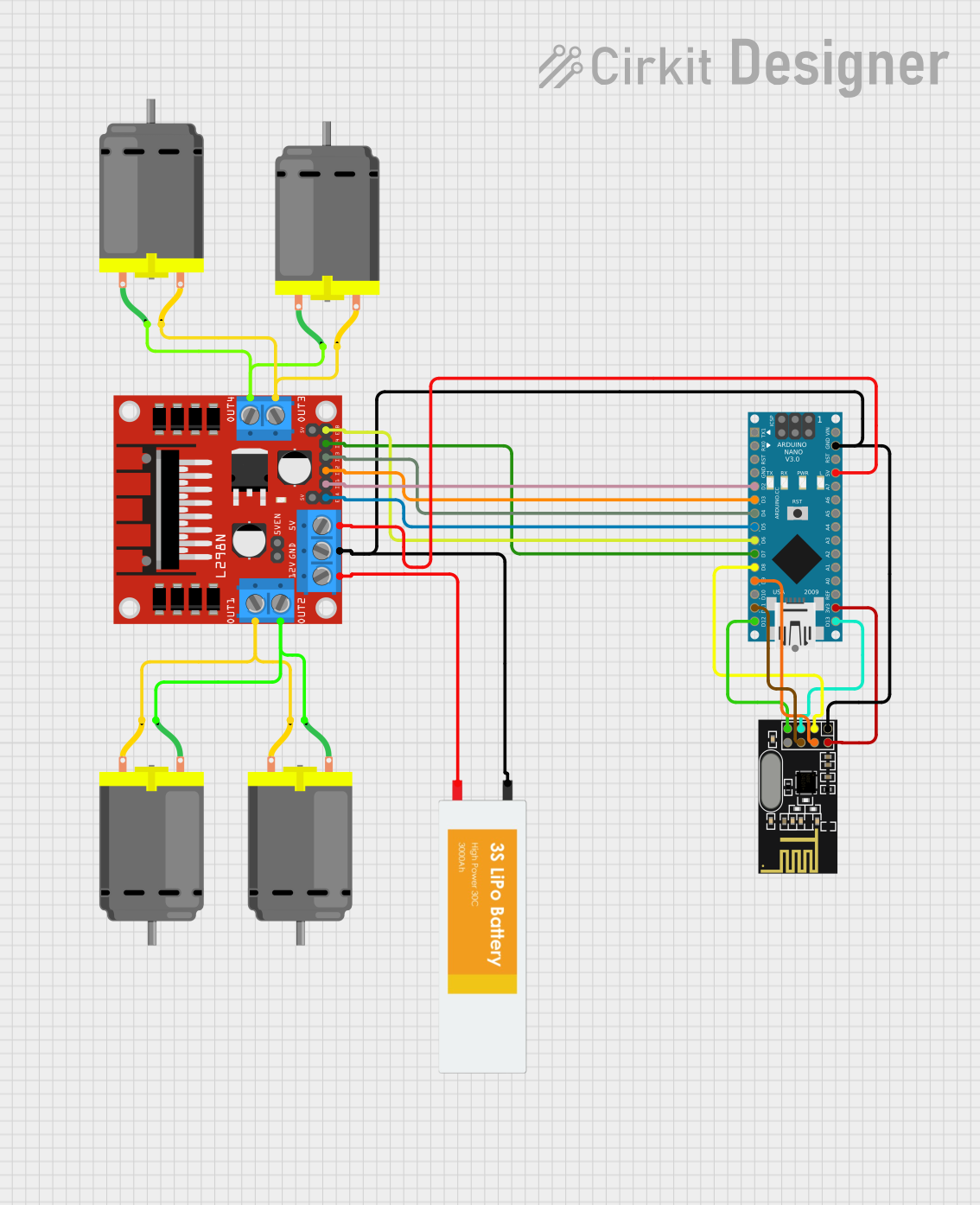
Circuit Documentation
Summary
The circuit in question is designed to control a set of DC motors using an Arduino Nano microcontroller in conjunction with an L298N DC motor driver. The system also includes an NRF24L01 module for wireless communication, allowing remote control of the motors. A Lipo battery provides the power source for the circuit. The Arduino Nano is programmed to interpret signals received from the NRF24L01 module and accordingly drive the motors via the L298N motor driver.
Component List
DC Motor
- Description: A standard DC motor used for converting electrical energy into mechanical rotation.
- Pins: pin 1, pin 2
L298N DC Motor Driver
- Description: A motor driver module capable of driving a couple of DC motors. It controls the direction and speed of the motors.
- Pins: OUT1, OUT2, 12V, GND, 5V, OUT3, OUT4, 5V-ENA-JMP-I, 5V-ENA-JMP-O, +5V-J1, +5V-J2, ENA, IN1, IN2, IN3, IN4, ENB
Arduino Nano
- Description: A small, complete, and breadboard-friendly board based on the ATmega328 (Arduino Nano 3.x). It has more or less the same functionality of the Arduino Duemilanove, but in a different package.
- Pins: D1/TX, D0/RX, RESET, GND, D2, D3, D4, D5, D6, D7, D8, D9, D10, D11/MOSI, D12/MISO, VIN, 5V, A7, A6, A5, A4, A3, A2, A1, A0, AREF, 3V3, D13/SCK
NRF24L01
- Description: A wireless transceiver module that operates in the 2.4GHz band. It is used for wireless communication between devices.
- Pins: IRQ (not used), MOSI, CSN, VCC (3V), GND, CE, SCK, MISO
Lipo Battery
- Description: A rechargeable battery of lithium-ion technology, providing a power source for the circuit.
- Pins: VCC, GND
Wiring Details
DC Motor
- pin 1: Connected to L298N DC motor driver OUT2 or OUT4
- pin 2: Connected to L298N DC motor driver OUT1 or OUT3
L298N DC Motor Driver
- OUT1, OUT2, OUT3, OUT4: Connected to DC Motor pin 1 and pin 2
- 12V: Connected to Lipo Battery VCC
- GND: Common ground with Arduino Nano, NRF24L01, and Lipo Battery
- 5V: Connected to Arduino Nano 5V
- ENA, ENB: Connected to Arduino Nano D5 and D6 respectively
- IN1, IN2, IN3, IN4: Connected to Arduino Nano D2, D3, D4, and D7 respectively
Arduino Nano
- D2, D3, D4, D5, D6, D7: Connected to L298N DC motor driver IN1, IN2, IN3, ENA, ENB, IN4 respectively
- D8, D9: Connected to NRF24L01 CE, CSN respectively
- D11/MOSI, D12/MISO, D13/SCK: Connected to NRF24L01 MOSI, MISO, SCK respectively
- GND: Common ground with L298N DC motor driver, NRF24L01, and Lipo Battery
- 5V: Connected to L298N DC motor driver 5V
- 3V3: Connected to NRF24L01 VCC (3V)
NRF24L01
- CE, CSN: Connected to Arduino Nano D8, D9 respectively
- MOSI, MISO, SCK: Connected to Arduino Nano D11/MOSI, D12/MISO, D13/SCK respectively
- VCC (3V): Connected to Arduino Nano 3V3
- GND: Common ground with Arduino Nano, L298N DC motor driver, and Lipo Battery
Lipo Battery
- VCC: Connected to L298N DC motor driver 12V
- GND: Common ground with Arduino Nano, L298N DC motor driver, and NRF24L01
Documented Code
#include <SPI.h>
#include <nRF24L01.h>
#include <RF24.h>

//#define PRINT_DEBUG   //Uncomment this line if you want to print the values on serial monitor

#define SIGNAL_TIMEOUT 500  // This is signal timeout in milli seconds.

const uint64_t pipeIn = 0xF9E8F0F0E1LL;
RF24 radio(8, 9);
unsigned long lastRecvTime = 0;

struct PacketData
{
  byte xAxisValue;
  byte yAxisValue;
} receiverData;

//Right motor
int enableRightMotor=5;
int rightMotorPin1=2;
int rightMotorPin2=3;

//Left motor
int enableLeftMotor=6;
int leftMotorPin1=4;
int leftMotorPin2=7;

void setup()
{
  pinMode(enableRightMotor,OUTPUT);
  pinMode(rightMotorPin1,OUTPUT);
  pinMode(rightMotorPin2,OUTPUT);

  pinMode(enableLeftMotor,OUTPUT);
  pinMode(leftMotorPin1,OUTPUT);
  pinMode(leftMotorPin2,OUTPUT);

  rotateMotor(0,0);

  radio.begin();
  radio.setDataRate(RF24_250KBPS);
  radio.openReadingPipe(1,pipeIn);
  radio.startListening(); //start the radio receiver

  #ifdef PRINT_DEBUG
    Serial.begin(115200);
  #endif
}

void loop()
{
    int rightMotorSpeed=0;
    int leftMotorSpeed=0;
    // Check if RF is connected and packet is available
    if(radio.isChipConnected() && radio.available())
    {
      radio.read(&receiverData, sizeof(PacketData));
      int mappedYValue = map(receiverData.yAxisValue, 0, 254, -255, 255);
      int mappedXValue = map(receiverData.xAxisValue, 0, 254, -255, 255);
      int motorDirection = 1;
      if (mappedYValue < 0)
      {
        motorDirection = -1;
      }

      rightMotorSpeed = abs(mappedYValue) - mappedXValue;
      leftMotorSpeed = abs(mappedYValue) + mappedXValue;

      rightMotorSpeed = constrain(rightMotorSpeed, 0, 255);
      leftMotorSpeed = constrain(leftMotorSpeed, 0, 255);

      rotateMotor(rightMotorSpeed * motorDirection, leftMotorSpeed * motorDirection);

      lastRecvTime = millis();

      #ifdef PRINT_DEBUG
        Serial.println(receiverData.xAxisValue);
        Serial.println(receiverData.yAxisValue);
      #endif
    }
    else
    {
      //Signal lost. Reset the motor to stop
      unsigned long now = millis();
      if ( now - lastRecvTime > SIGNAL_TIMEOUT )
      {
        rotateMotor(0, 0);
     }
   }
}

void rotateMotor(int rightMotorSpeed, int leftMotorSpeed)
{
  if (rightMotorSpeed < 0)
  {
    digitalWrite(rightMotorPin1,LOW);
    digitalWrite(rightMotorPin2,HIGH);
  }
  else if (rightMotorSpeed > 0)
  {
    digitalWrite(rightMotorPin1,HIGH);
    digitalWrite(rightMotorPin2,LOW);
  }
  else
  {
    digitalWrite(rightMotorPin1,LOW);
    digitalWrite(rightMotorPin2,LOW);
  }

  if (leftMotorSpeed < 0)
  {
    digitalWrite(leftMotorPin1,LOW);
    digitalWrite(leftMotorPin2,HIGH);
  }
  else if (leftMotorSpeed > 0)
  {
    digitalWrite(leftMotorPin1,HIGH);
    digitalWrite(leftMotorPin2,LOW);
  }
  else
  {
    digitalWrite(leftMotorPin1,LOW);
    digitalWrite(leftMotorPin2,LOW);
  }

  analogWrite(enableRightMotor, abs(rightMotorSpeed));
  analogWrite(enableLeftMotor, abs(leftMotorSpeed));
}
This code is responsible for setting up the Arduino Nano to communicate with the NRF24L01 module and control the DC motors through the L298N motor driver. It includes a structure to hold the packet data received from the NRF24L01 module, functions to initialize the system, and a loop that continuously checks for incoming data to control the motors. The rotateMotor function is used to set the direction and speed of the motors based on the received data.