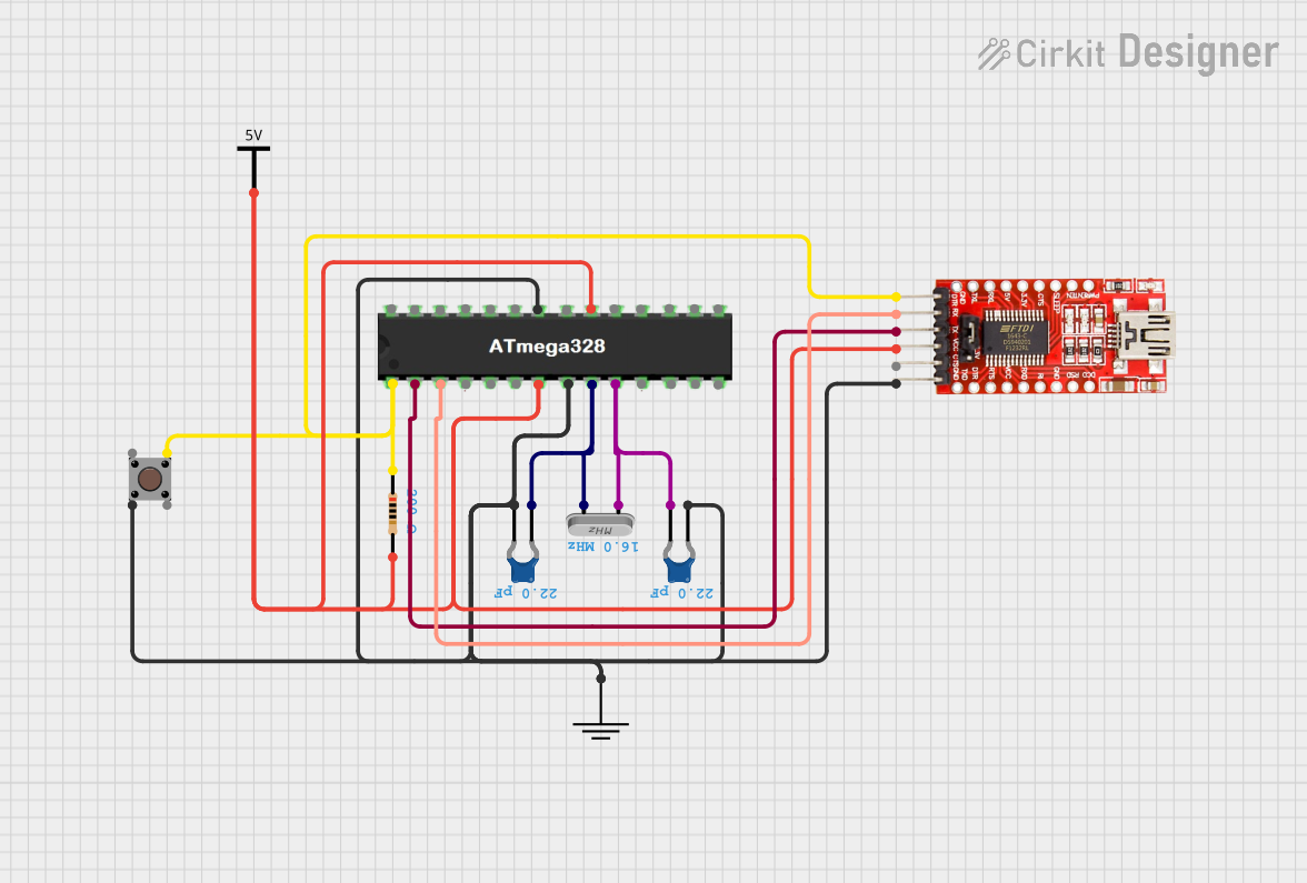
ATMEGA328 Microcontroller Circuit with Serial Programming Interface

Circuit Documentation
Summary
The circuit in question appears to be designed around the ATMEGA328 microcontroller, which is commonly used in Arduino-based projects. The circuit includes basic components for microcontroller operation, such as a crystal for clock generation, capacitors for decoupling, a resistor, and a pushbutton that may serve as a reset or user input. Additionally, an FTDI Programmer is included, suggesting that the circuit is intended to be interfaced with a computer for programming or serial communication. The absence of embedded code indicates that the microcontroller's firmware is not provided or is to be developed separately.
Component List
Ceramic Capacitors
- Description: These capacitors are likely used for decoupling purposes, providing a stable voltage supply to the microcontroller by filtering out noise from the power supply.
- Capacitance: 22 pF (2.2e-11 Farads)
Crystal
- Description: This component provides a clock signal to the microcontroller, which is essential for timing operations and executing code at a consistent speed.
ATMEGA328 Microcontroller
- Description: The central processing unit of the circuit, which will run the user's code and control other components.
GND (Ground)
- Description: This is a common reference point for all voltage levels in the circuit.
Resistor
- Description: This resistor may be used as a pull-up or pull-down, or to limit current in a particular part of the circuit.
- Resistance: 200 Ohms
FTDI Programmer
- Description: This module is used to program the ATMEGA328 microcontroller and to facilitate serial communication with a computer.
Vcc (Power Supply)
- Description: This represents the positive voltage supply for the circuit.
Pushbutton
- Description: A user interface component that can be used to trigger events or reset the microcontroller.
Wiring Details
Ceramic Capacitors
- Connected between the ATMEGA328's crystal pins and the crystal oscillator.
- Also connected to ground.
Crystal
- Connected to the ATMEGA328's crystal pins with capacitors to ground on each pin.
ATMEGA328 Microcontroller
- Crystal pins connected to the crystal oscillator with capacitors to ground.
- Ground pin connected to the FTDI Programmer's ground, the pushbutton, and the ground reference.
- Reset pin connected through a resistor to the FTDI Programmer's DTR pin and to a pushbutton.
- D0 and D1 pins connected to the FTDI Programmer's TX and RX pins for serial communication.
- VCC pins connected to the FTDI Programmer's VCC pin and the power supply.
GND (Ground)
- Connected to the ATMEGA328's ground pin, the FTDI Programmer's ground pin, and the ceramic capacitors.
Resistor
- Connected between the ATMEGA328's reset pin and the FTDI Programmer's DTR pin.
FTDI Programmer
- DTR pin connected through a resistor to the ATMEGA328's reset pin.
- RX and TX pins connected to the ATMEGA328's D0 and D1 pins for serial communication.
- VCC and ground pins connected to the power supply and ground reference.
Vcc (Power Supply)
- Connected to the ATMEGA328's VCC pins and the FTDI Programmer's VCC pin.
Pushbutton
- One side connected to the ATMEGA328's reset pin through a resistor.
- The other side connected to ground.
Documented Code
No code has been provided for the ATMEGA328 microcontroller. The firmware for this microcontroller needs to be developed and uploaded using the FTDI Programmer. The code would typically be written in C or C++ using an IDE such as the Arduino IDE or Atmel Studio. Once the code is developed, it should be documented here with explanations for each function and routine.