
Arduino-Controlled NEMA23 Stepper Motor with A4988 Driver and Adjustable Speed
View and Edit Project In Cirkit Designer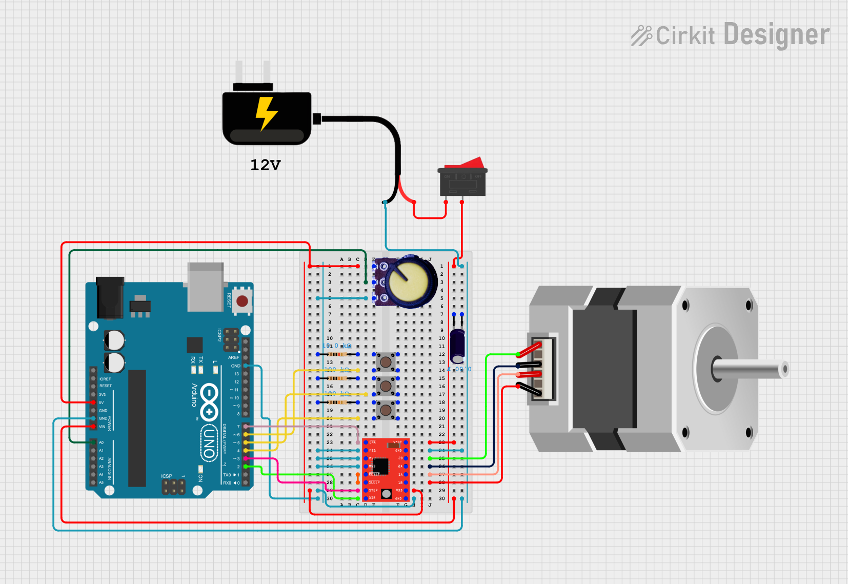
Circuit Documentation
Summary
This circuit is designed to control a NEMA23 stepper motor using an A4988 Stepper Motor Driver. The Arduino UNO serves as the main microcontroller to interface with the driver and manage the motor's steps and direction. User inputs are captured through pushbuttons and a potentiometer, which likely adjust the motor's operation parameters. The circuit includes resistors for potential voltage division or pull-up/pull-down configurations, and an electrolytic capacitor to stabilize the voltage supply to the motor driver. A DC Source provides power to the system, and a rocker switch is used to control the power flow.
Component List
A4988 Stepper Motor Driver (Red)
- Controls the NEMA23 stepper motor.
- Pins: ENABLE, MS1, MS2, MS3, RESET, SLEEP, STEP, DIR, VMOT, GND, 2B, 2A, 1A, 1B, VDD
Resistors
- Three resistors with different resistance values.
- Resistance: 10k Ohms, 100k Ohms, 100k Ohms
Pushbuttons
- Three pushbuttons likely used for user input to control motor operation.
Potentiometer
- Provides an adjustable voltage that may be used for setting motor speed or other parameters.
Arduino UNO
- The main microcontroller that interfaces with the motor driver and other components.
NEMA23 Stepper Motor
- The actuator in the system, controlled by the A4988 driver.
Electrolytic Capacitor
- Used for voltage smoothing on the motor driver's power supply.
DC Source 9V
- Provides power to the circuit.
Rocker Switch
- Manages the power supply to the circuit.
Wiring Details
A4988 Stepper Motor Driver (Red)
- ENABLE connected to Arduino UNO D7
- MS1, MS2, MS3 connected to VCC through resistors
- RESET connected to SLEEP
- STEP connected to Arduino UNO D3
- DIR connected to Arduino UNO D2
- VMOT connected to the positive side of the Electrolytic Capacitor and through the Rocker Switch to the DC Source 9V
- GND connected to the negative side of the Electrolytic Capacitor and to the Arduino UNO GND
- 2B connected to NEMA23 A
- 2A connected to NEMA23 C
- 1A connected to NEMA23 B
- 1B connected to NEMA23 D
- VDD connected to Arduino UNO 5V
Resistors
- 10k Ohm resistor connected between Potentiometer VCC and Pushbutton Pin 3 (out)
- 100k Ohm resistors connected between Potentiometer VCC and Pushbutton Pin 3 (out) for the other two pushbuttons
Pushbuttons
- Pin 1 (in) of each pushbutton connected to Arduino UNO D4, D5, and D6 respectively
- Pin 3 (out) of each pushbutton connected to one side of the corresponding resistor
Potentiometer
- GND connected to Arduino UNO GND
- Output connected to Arduino UNO A0
- VCC connected to the resistors and pushbuttons as described above
Arduino UNO
- 5V and GND used for power distribution
- A0 used to read the potentiometer output
- D2, D3, D4, D5, D6, D7 used to interface with the A4988 driver and pushbuttons
- Vin connected to the positive side of the Electrolytic Capacitor through the Rocker Switch
NEMA23 Stepper Motor
- Connected to the A4988 driver as described above
Electrolytic Capacitor
- Placed across the VMOT and GND of the A4988 driver to stabilize the power supply
DC Source 9V
- Provides power to the circuit through the Rocker Switch
Rocker Switch
- Controls the connection between the DC Source 9V and the rest of the circuit
Documented Code
void setup() {
  // put your setup code here, to run once:

}

void loop() {
  // put your main code here, to run repeatedly:

}
The provided code is a template with empty setup() and loop() functions. The setup() function is intended for initialization code that runs once when the Arduino is powered on or reset. The loop() function contains the main logic of the program, which runs repeatedly as long as the Arduino is powered. Specific functionality needs to be implemented within these functions to control the stepper motor using the A4988 driver based on the inputs from the potentiometer and pushbuttons.