Cirkit Designer
Your all-in-one circuit design IDE
Home /
Project Documentation
Arduino-Controlled Dual DC Motor Driver with Bluetooth Interface
Circuit Documentation
Summary of the Circuit
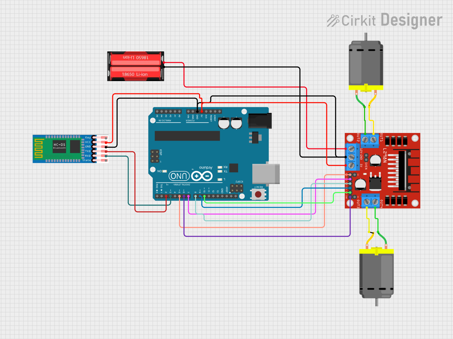
This circuit is designed to control two DC motors using an Arduino UNO microcontroller and an L298N DC motor driver. The circuit also includes an HC-05 Bluetooth module for wireless communication and an 18650 Li-Ion battery to provide power. The Arduino UNO interfaces with the L298N driver to control the speed and direction of the motors, and it communicates with the HC-05 module to receive control commands wirelessly.
Component List
Arduino UNO
- Microcontroller board based on the ATmega328P
- It has 14 digital input/output pins, 6 analog inputs, a 16 MHz quartz crystal, a USB connection, a power jack, an ICSP header, and a reset button.
L298N DC Motor Driver
- A dual H-bridge motor driver that can drive two DC motors or one stepper motor.
- It has pins for motor power supply, ground, control inputs, and motor outputs.
18650 Li-Ion Battery
- A rechargeable battery providing a nominal voltage of 3.7V (up to 4.2V when fully charged).
- It has a positive and a negative terminal for power supply.
DC Motor (x2)
- Standard DC motors with two connection pins.
- Used for converting electrical energy into mechanical motion.
HC-05 Bluetooth Module
- A wireless communication module that can be used for serial communication.
- It has pins for enabling, power supply, ground, and TX/RX for serial data.
Wiring Details
Arduino UNO
5VandGNDare connected to the 5V and ground buses, respectively, providing power to the HC-05 Bluetooth module and the L298N motor driver.- Digital pins
D2toD10are used to interface with the HC-05 module and the L298N motor driver for control signals.
L298N DC Motor Driver
5Vis connected to the 5V power bus from the Arduino UNO.GNDis connected to the ground bus.12Vis connected to the positive terminal of the 18650 Li-Ion battery.IN1toIN4are connected to Arduino UNO digital pinsD7toD10for motor control signals.ENAandENBare connected to Arduino UNO digital pinsD5andD6for enabling the motor driver channels.OUT1toOUT4are connected to the respective pins of the two DC motors to drive them.
18650 Li-Ion Battery
Positiveterminal is connected to the12Vinput of the L298N motor driver to power the motors.Negativeterminal is connected to the ground bus.
DC Motors
- Each motor has two pins connected to the
OUT1/OUT2andOUT3/OUT4outputs of the L298N motor driver, respectively.
HC-05 Bluetooth Module
VCCis connected to the 5V power bus.GNDis connected to the ground bus.TXDandRXDare connected to Arduino UNO digital pinsD2andD3for serial communication.
Documented Code
Arduino UNO Code (sketch.ino)
void setup() {
  // put your setup code here, to run once:

}

void loop() {
  // put your main code here, to run repeatedly:

}
Note: The provided code is a template and does not contain any functional code to control the motors or communicate with the HC-05 Bluetooth module. The user is expected to fill in the setup and loop functions with the necessary code to implement the desired functionality.