Cirkit Designer
Your all-in-one circuit design IDE
Home /
Project Documentation
WiFi-Enabled OLED Display with ESP8266

Circuit Documentation
Summary of the Circuit
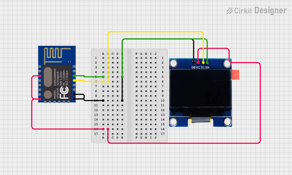
This circuit integrates an ESP8266 ESP-12E WiFi Module with an OLED 1.3" display. The ESP8266 module is responsible for wireless communication and control logic, while the OLED display provides a visual interface for displaying data. The ESP8266 is configured to communicate with the OLED display via the I2C protocol, using its GPIO_4 and GPIO_5 pins as SCL (Serial Clock) and SDA (Serial Data) lines, respectively.
Component List
ESP8266 ESP-12E WiFi Module
- Description: A WiFi module that offers a complete and self-contained Wi-Fi networking solution, allowing it to either host the application or offload all Wi-Fi networking functions from another application processor.
- Pins: GND, GPIO_15, GPIO_2, GPIO_0, GPIO_4, GPIO_5, RXD, TXD, REST, ADC_0, CH_PD, GPIO_16, GPIO_14, GPIO_12, GPIO_13, VCC, SCLK, MOSI, GPIO_10, GPIO_9, MISO, CS0
OLED 1.3" Display
- Description: A small display that uses OLED technology to provide a high-contrast, high-resolution visual output.
- Pins: GND, VCC, SCL, SDA
Wiring Details
ESP8266 ESP-12E WiFi Module
- GND connected to OLED GND
- GPIO_4 (SCL) connected to OLED SCL
- GPIO_5 (SDA) connected to OLED SDA
- CH_PD and VCC connected together and to OLED VCC
OLED 1.3" Display
- GND connected to ESP8266 GND
- VCC connected to ESP8266 VCC and CH_PD
- SCL connected to ESP8266 GPIO_4
- SDA connected to ESP8266 GPIO_5
Documented Code
Microcontroller: ESP8266 ESP-12E WiFi Module
File: sketch.ino
void setup() {
  // put your setup code here, to run once:

}

void loop() {
  // put your main code here, to run repeatedly:

}
File: documentation.txt
(No additional documentation provided for this file)
This concludes the documentation for the given circuit. The ESP8266 module is the central controller and is wired to communicate with the OLED display for data visualization. The provided code is a template and should be further developed to implement the desired functionality.