Arduino UNO Controlled Dual Joystick Servo Manipulator
Circuit Documentation
Summary
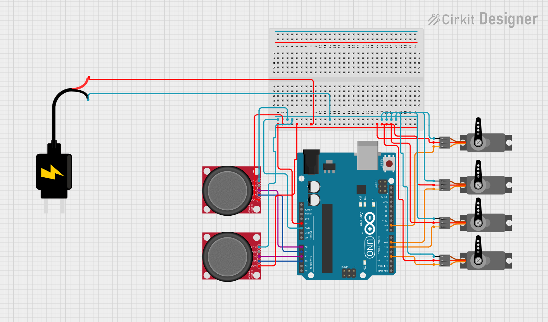
This circuit integrates an Arduino UNO with two analog joysticks and four servo motors. The Arduino UNO serves as the central processing unit, reading the joystick positions and controlling the servo motors accordingly. The circuit is powered by a 5V DC source, which supplies power to the Arduino, joysticks, and servos. The joysticks are used to provide analog input to the Arduino, which then translates these inputs into movements for the servo motors.
Component List
Arduino UNO
- Microcontroller board based on the ATmega328P
- It has 14 digital input/output pins, 6 analog inputs, a 16 MHz quartz crystal, a USB connection, a power jack, an ICSP header, and a reset button.
Analog Joystick (Wokwi Compatible)
- Two-axis analog input joystick with a push-button
- Provides analog feedback based on the position of the joystick along the horizontal (HORZ) and vertical (VERT) axes.
Servo
- A rotary actuator or linear actuator that allows for precise control of angular or linear position, velocity, and acceleration.
- It consists of a suitable motor coupled to a sensor for position feedback.
DC Source 5V
- A power supply module that provides a regulated 5V output.
- Used to power the components in the circuit.
Wiring Details
Arduino UNO
- 5V pin connected to the VCC pins of both joysticks and all servo motors, as well as the VCC pin of the 5V DC source.
- GND pin connected to the GND pins of both joysticks, all servo motors, and the GND pin of the 5V DC source.
- A0 pin connected to the HORZ pin of the first joystick.
- A1 pin connected to the VERT pin of the first joystick.
- A2 pin connected to the HORZ pin of the second joystick.
- A3 pin connected to the VERT pin of the second joystick.
- D9, D6, D5, D3 pins connected to the PWM pins of the servo motors.
Analog Joystick (Wokwi Compatible)
- VCC pin connected to the 5V output from the Arduino UNO.
- GND pin connected to the ground (GND) on the Arduino UNO.
- HORZ and VERT pins connected to the respective analog input pins on the Arduino UNO.
- SEL pin (if used) would typically be connected to a digital input pin on the Arduino UNO for the push-button feature.
Servo
- VCC pin connected to the 5V output from the Arduino UNO.
- GND pin connected to the ground (GND) on the Arduino UNO.
- PWM pin connected to a digital output pin on the Arduino UNO capable of PWM.
DC Source 5V
- VCC pin providing 5V to the Arduino UNO and other components.
- GND pin connected to the common ground in the circuit.
Documented Code
void setup() {
  // put your setup code here, to run once:

}

void loop() {
  // put your main code here, to run repeatedly:

}
The provided code is a template with empty setup() and loop() functions. The setup() function is intended for initialization code that runs once when the program starts, such as configuring pin modes. The loop() function is for the main logic of the Arduino sketch, which runs repeatedly as long as the Arduino is powered.
For this circuit, the setup() function would typically initialize the servo objects and configure the analog inputs. The loop() function would read the joystick positions using analogRead() and then map these values to control the position of the servo motors using servo.write() or similar functions. However, the specific implementation details are not provided in the input code.