
Arduino-Controlled Robotic Vehicle with IR Sensors and L298N Motor Driver
View and Edit Project In Cirkit Designer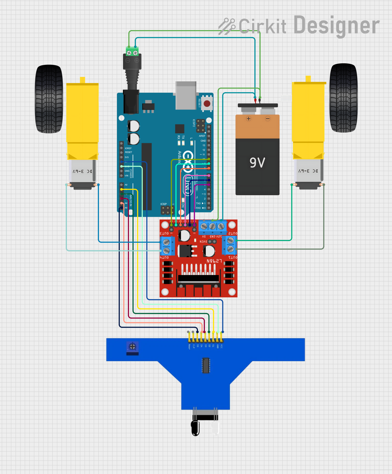
Circuit Documentation
Summary
This circuit is designed to interface an Arduino UNO microcontroller with a 5-channel IR sensor and control two DC gearmotors through an L298N DC motor driver. The circuit is powered by a 9V battery connected through a 2.1mm barrel jack with a terminal block. The Arduino UNO reads sensor inputs from the IR sensor and outputs control signals to the L298N driver, which in turn drives the left and right gearmotors.
Component List
Gearmotor DC Wheels Right
- Description: A DC gearmotor used for the right wheel of a mobile platform.
- Pins: PIN1, PIN2
Gearmotor DC Wheels Left
- Description: A DC gearmotor used for the left wheel of a mobile platform.
- Pins: PIN1, PIN2
Battery 9V
- Description: A 9V battery providing the power source for the circuit.
- Pins: VCC, GND
2.1mm Barrel Jack with Terminal Block
- Description: A connector for the 9V battery to interface with the circuit.
- Pins: POS, NEG
L298N DC Motor Driver
- Description: A motor driver module used to control the speed and direction of two DC motors.
- Pins: OUT1, OUT2, 12V, GND, 5V, OUT3, OUT4, 5V-ENA-JMP-I, 5V-ENA-JMP-O, +5V-J1, +5V-J2, ENA, IN1, IN2, IN3, IN4, ENB
Arduino UNO
- Description: A microcontroller board based on the ATmega328P, used for processing and controlling the components in the circuit.
- Pins: UNUSED, IOREF, Reset, 3.3V, 5V, GND, Vin, A0, A1, A2, A3, A4, A5, SCL, SDA, AREF, D13, D12, D11, D10, D9, D8, D7, D6, D5, D4, D3, D2, D1, D0
5 Channel IR Sensor
- Description: An infrared sensor with 5 channels used for line tracking or obstacle detection.
- Pins: VCC, GND, S1, S2, S3, S4, S5, CLP, Near
Wiring Details
Gearmotor DC Wheels Right
- PIN1: Connected to OUT4 on L298N DC Motor Driver
- PIN2: Connected to OUT3 on L298N DC Motor Driver
Gearmotor DC Wheels Left
- PIN1: Connected to OUT2 on L298N DC Motor Driver
- PIN2: Connected to OUT1 on L298N DC Motor Driver
Battery 9V
- VCC: Connected to POS on 2.1mm Barrel Jack and 12V on L298N DC Motor Driver
- GND: Connected to NEG on 2.1mm Barrel Jack and GND on L298N DC Motor Driver
2.1mm Barrel Jack with Terminal Block
- POS: Connected to VCC on Battery 9V and 12V on L298N DC Motor Driver
- NEG: Connected to GND on Battery 9V and GND on L298N DC Motor Driver
L298N DC Motor Driver
- OUT1, OUT2: Connected to Gearmotor DC Wheels Left
- OUT3, OUT4: Connected to Gearmotor DC Wheels Right
- 12V: Connected to VCC on Battery 9V
- GND: Connected to GND on Battery 9V
- ENA, IN1, IN2: Controlled by Arduino UNO (D5, D6, D7)
- ENB, IN3, IN4: Controlled by Arduino UNO (D10, D8, D9)
Arduino UNO
- 5V: Connected to VCC on 5 Channel IR Sensor
- GND: Connected to GND on 5 Channel IR Sensor
- A1-A5: Connected to S1-S5 on 5 Channel IR Sensor
- D5-D10: Control signals to L298N DC Motor Driver
5 Channel IR Sensor
- VCC: Connected to 5V on Arduino UNO
- GND: Connected to GND on Arduino UNO
- S1-S5: Connected to A1-A5 on Arduino UNO
Documented Code
Arduino UNO Code (sketch.ino)
void setup() {
  // put your setup code here, to run once:

}

void loop() {
  // put your main code here, to run repeatedly:

}
Note: The provided code is a template and does not contain any functional code to control the motors or read the sensor inputs. This will need to be implemented based on the specific requirements of the application.