
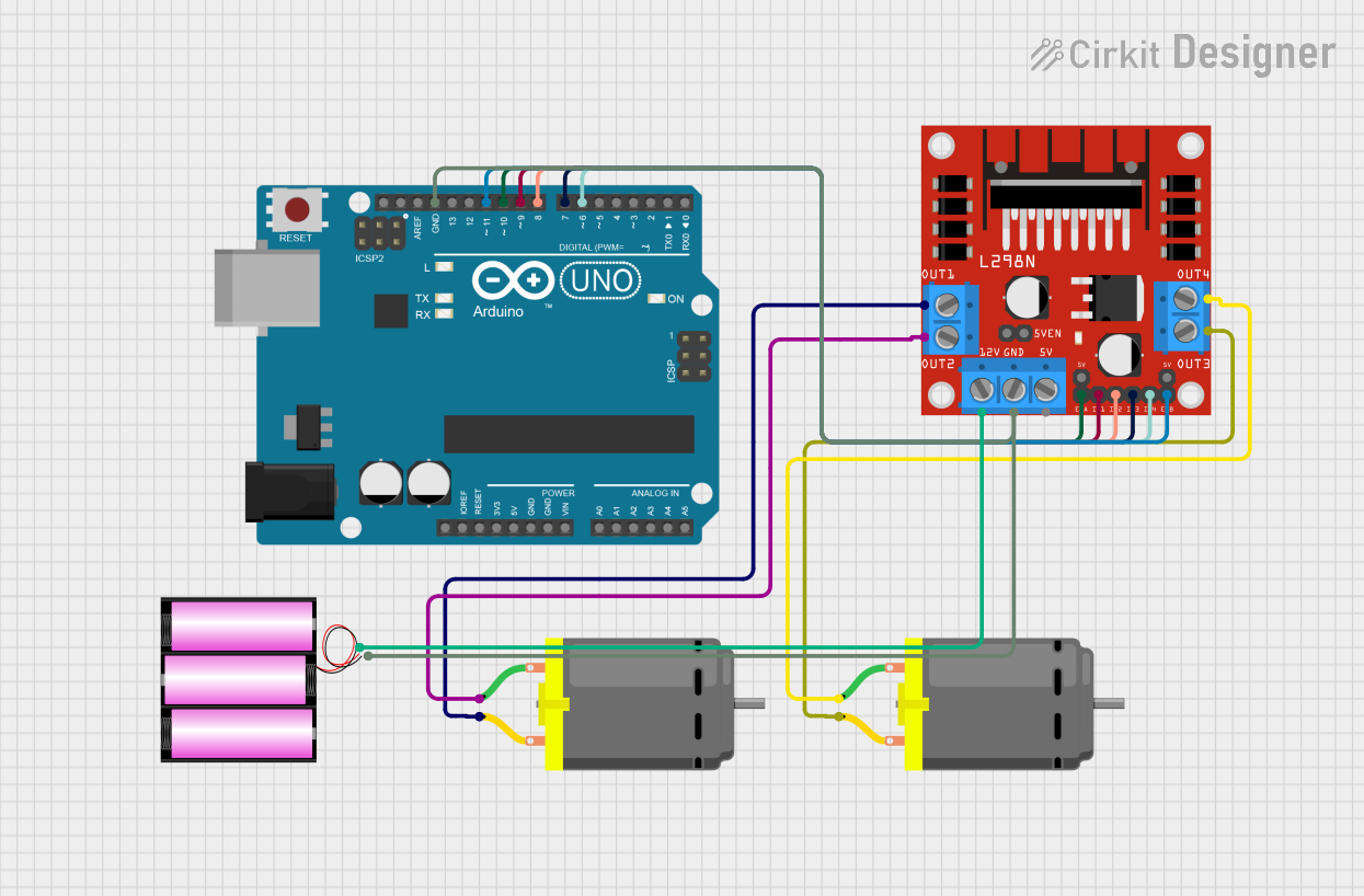
Circuit Documentation
Summary of the Circuit
This circuit is designed to control two DC motors using an Arduino UNO microcontroller and an L298N DC motor driver. The Arduino UNO interfaces with the L298N driver to regulate the speed and direction of the motors. A 12V battery provides the necessary power for the motors and the motor driver, while the Arduino is powered through its voltage regulator.
Component List
Arduino UNO
- Description: A microcontroller board based on the ATmega328P.
- Pins: UNUSED, IOREF, Reset, 3.3V, 5V, GND, Vin, A0-A5, SCL, SDA, AREF, D0-D13.
Battery 12V
- Description: A 12-volt power source for the circuit.
- Pins: + (positive), - (negative).
L298N DC Motor Driver
- Description: A module for controlling up to two DC motors with direction and speed control.
- Pins: OUT1, OUT2, 12V, GND, 5V, OUT3, OUT4, 5V-ENA-JMP-I, 5V-ENA-JMP-O, +5V-J1, +5V-J2, ENA, IN1, IN2, IN3, IN4, ENB.
DC Motor (x2)
- Description: The actuators that are driven by the motor driver.
- Pins: pin 1, pin 2.
Wiring Details
Arduino UNO
- GND connected to the GND of the battery and the GND of the L298N motor driver.
- D11 connected to ENB on the L298N motor driver.
- D10 connected to ENA on the L298N motor driver.
- D9 connected to IN1 on the L298N motor driver.
- D8 connected to IN2 on the L298N motor driver.
- D7 connected to IN3 on the L298N motor driver.
- D6 connected to IN4 on the L298N motor driver.
Battery 12V
-
- (positive) connected to the 12V input of the L298N motor driver.
-
- (negative) connected to the GND of the Arduino UNO and the GND of the L298N motor driver.
L298N DC Motor Driver
- GND connected to the GND of the Arduino UNO and the - (negative) of the battery.
- 12V connected to the + (positive) of the battery.
- ENA connected to D10 on the Arduino UNO.
- ENB connected to D11 on the Arduino UNO.
- IN1 connected to D9 on the Arduino UNO.
- IN2 connected to D8 on the Arduino UNO.
- IN3 connected to D7 on the Arduino UNO.
- IN4 connected to D6 on the Arduino UNO.
- OUT1 connected to pin 2 of the first DC Motor.
- OUT2 connected to pin 1 of the first DC Motor.
- OUT3 connected to pin 2 of the second DC Motor.
- OUT4 connected to pin 1 of the second DC Motor.
DC Motor 1
- pin 1 connected to OUT2 on the L298N motor driver.
- pin 2 connected to OUT1 on the L298N motor driver.
DC Motor 2
- pin 1 connected to OUT4 on the L298N motor driver.
- pin 2 connected to OUT3 on the L298N motor driver.
Documented Code
Arduino UNO Code (sketch.ino)
void setup() {
  // put your setup code here, to run once:

}

void loop() {
  // put your main code here, to run repeatedly:

}
Note: The provided code is a template and does not contain any functional code to control the motors. It needs to be populated with the appropriate setup and loop code to initialize the motor driver pins and to control the motors.
Additional Files
- documentation.txt: This file is mentioned but no content was provided. It is likely intended for additional notes or manual documentation.