
Circuit Documentation
Summary of the Circuit
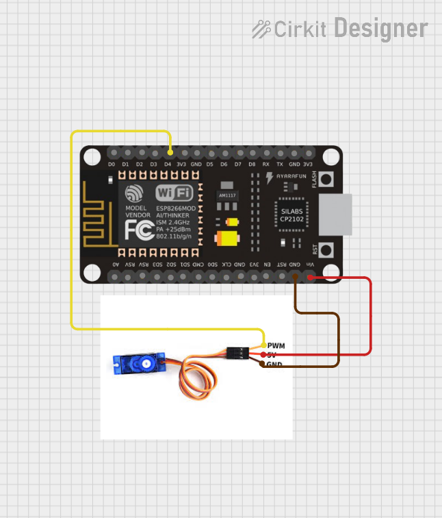
This circuit consists of an ESP8266 NodeMCU microcontroller unit (MCU) interfaced with an SG90 servo motor. The ESP8266 NodeMCU is responsible for controlling the servo motor by sending Pulse Width Modulation (PWM) signals to the servo's control pin. The servo motor is powered directly from the NodeMCU, with the ground and power connections shared between the two components. This setup is typically used in applications where precise angular movement is required, such as in robotics or automated systems.
Component List
ESP8266 NodeMCU
- Description: A Wi-Fi capable microcontroller module based on the ESP8266 chip.
- Pins: D0, D1, D2, D3, D4, 3V3, GND, D5, D6, D7, D8, RX, TX, A0, RSV, SD3, SD2, SD1, CMD, SD0, CLK, EN, RST, VIN
- Purpose: Acts as the main controller for the circuit, providing logic and Wi-Fi connectivity.
SG90 Servo Motor
- Description: A small and lightweight servo motor capable of precise control.
- Pins: PWM, 5V, GND
- Purpose: Executes physical movements based on PWM signals received from the ESP8266 NodeMCU.
Wiring Details
ESP8266 NodeMCU
- D4: Connected to the PWM pin of the SG90 servo motor for control signals.
- GND: Common ground shared with the SG90 servo motor.
- VIN: Provides power to the SG90 servo motor by connecting to its 5V pin.
SG90 Servo Motor
- PWM: Receives control signals from the D4 pin of the ESP8266 NodeMCU.
- 5V: Powered by the VIN pin of the ESP8266 NodeMCU.
- GND: Shares a common ground with the ESP8266 NodeMCU.
Documented Code
There is no code provided for the microcontroller in this circuit. To control the SG90 servo motor, code would typically be written to generate PWM signals on the ESP8266 NodeMCU's D4 pin. The code would define the angle of rotation for the servo motor and adjust the duty cycle of the PWM signal accordingly.
Please note that the actual implementation of the code would depend on the specific requirements of the application and the development environment used for programming the ESP8266 NodeMCU.