
Circuit Documentation
Summary
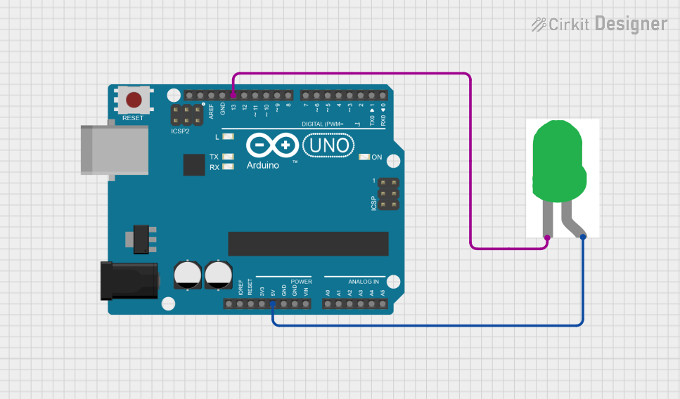
This document describes a simple circuit involving an Arduino UNO and a green LED. The LED is connected to the Arduino UNO such that its anode is connected to the 5V pin and its cathode is connected to the D13 pin. The Arduino UNO runs a sketch that blinks the LED on and off with a delay of 1 second.
Component List
Arduino UNO
- Description: A microcontroller board based on the ATmega328P.
- Pins: UNUSED, IOREF, Reset, 3.3V, 5V, GND, Vin, A0, A1, A2, A3, A4, A5, SCL, SDA, AREF, D13, D12, D11, D10, D9, D8, D7, D6, D5, D4, D3, D2, D1, D0
LED: Two Pin (green)
- Description: A green LED with two pins: anode and cathode.
- Pins: cathode, anode
Wiring Details
Arduino UNO
- 5V: Connected to the anode of the green LED.
- D13: Connected to the cathode of the green LED.
LED: Two Pin (green)
- anode: Connected to the 5V pin of the Arduino UNO.
- cathode: Connected to the D13 pin of the Arduino UNO.
Code
The following Arduino sketch controls the green LED connected to pin D13 of the Arduino UNO. The LED blinks on and off with a delay of 1 second.
/*
 * This Arduino sketch controls a single green LED connected to pin D13 of an
 * Arduino UNO. The LED is connected such that its cathode is connected to D13
 * and its anode is connected to the 5V pin. The sketch will blink the LED on
 * and off with a delay of 1 second.
 */

// Define the pin for the LED
const int ledPin = 13;

void setup() {
  // Initialize the digital pin as an output.
  pinMode(ledPin, OUTPUT);
}

void loop() {
  // Turn the LED on (HIGH is the voltage level)
  digitalWrite(ledPin, HIGH);
  // Wait for a second
  delay(1000);
  // Turn the LED off by making the voltage LOW
  digitalWrite(ledPin, LOW);
  // Wait for a second
  delay(1000);
}
File Name: sketch.ino