Raspberry Pi Pico Controlled Dual-Color LED Indicator

Circuit Documentation
Summary of the Circuit
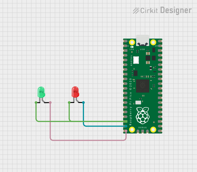
This circuit consists of a Raspberry Pi Pico microcontroller unit (MCU) interfaced with two LEDs: one green and one red. The Raspberry Pi Pico is responsible for controlling the state (on/off) of the LEDs through its GPIO pins. The green LED is connected to one of the GPIO pins of the Raspberry Pi Pico, and similarly, the red LED is connected to another GPIO pin. The circuit is designed to demonstrate basic GPIO control using the Raspberry Pi Pico.
Component List
Raspberry Pi Pico
- Description: A microcontroller board based on the RP2040 microcontroller chip.
- Purpose: Acts as the central processing unit of the circuit, controlling the LEDs.
- Pins: 43 GPIO pins, including power and ground.
LED: Two Pin (green)
- Description: A standard green LED with two pins: anode and cathode.
- Purpose: Serves as an indicator light when powered.
LED: Two Pin (red)
- Description: A standard red LED with two pins: anode and cathode.
- Purpose: Serves as an indicator light when powered.
Wiring Details
Raspberry Pi Pico
- Pin 18: Connected to the cathodes of both the green and red LEDs.
- Pin 19: Connected to the anode of the red LED.
- Pin 20: Connected to the anode of the green LED.
LED: Two Pin (green)
- Cathode: Connected to Raspberry Pi Pico pin 18.
- Anode: Connected to Raspberry Pi Pico pin 20.
LED: Two Pin (red)
- Cathode: Connected to Raspberry Pi Pico pin 18.
- Anode: Connected to Raspberry Pi Pico pin 19.
Documented Code
The following code is intended for the Raspberry Pi Pico microcontroller to control the LEDs. The code is written in C/C++ for the Arduino environment (.ino file).
void setup() {
  // Initialize the digital pin as an output for the red LED.
  pinMode(19, OUTPUT);
  // Initialize the digital pin as an output for the green LED.
  pinMode(20, OUTPUT);
}

void loop() {
  // Turn on the red LED.
  digitalWrite(19, HIGH);
  delay(1000); // Wait for a second.
  // Turn off the red LED.
  digitalWrite(19, LOW);

  // Turn on the green LED.
  digitalWrite(20, HIGH);
  delay(1000); // Wait for a second.
  // Turn off the green LED.
  digitalWrite(20, LOW);
}
This code sets up the Raspberry Pi Pico to alternate between turning the red and green LEDs on and off every second. The pinMode function is used to configure the pins connected to the LEDs as outputs, and the digitalWrite function is used to set the pins high (turn on the LED) or low (turn off the LED). The delay function is used to create a one-second interval between LED state changes.