Cirkit Designer
Your all-in-one circuit design IDE
Home /
Project Documentation
Battery-Powered Light-Activated LED Circuit with BC547 Transistor
Circuit Documentation
Summary
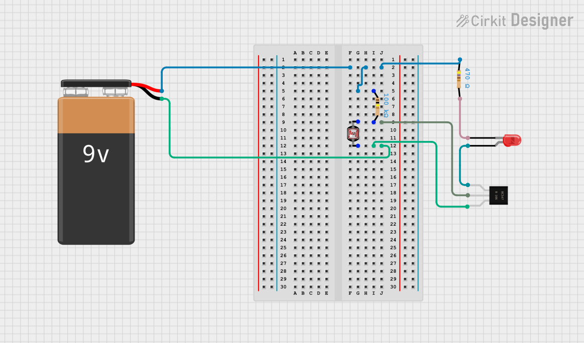
This circuit is a light-dependent LED driver. It uses a Light Dependent Resistor (LDR) to sense ambient light levels and a BC547 transistor to control the LED. When the ambient light level drops below a certain threshold, the LED will turn on. The circuit is powered by a 9V battery.
Component List
BC547 Transistor
- Description: NPN Bipolar Junction Transistor
- Pins: Collector, Base, Emitter
9V Battery
- Description: Power source
- Pins: Positive (+), Negative (-)
Resistor (470 Ohms)
- Description: Limits current to the LED
- Pins: Pin 1, Pin 2
- Properties: Resistance: 470 Ohms
Resistor (100k Ohms)
- Description: Forms a voltage divider with the LDR
- Pins: Pin 1, Pin 2
- Properties: Resistance: 100k Ohms
Photocell (LDR)
- Description: Light-dependent resistor
- Pins: Pin 0, Pin 1
LED (Red)
- Description: Light Emitting Diode
- Pins: Anode, Cathode
Wiring Details
BC547 Transistor
- Collector: Connected to the anode of the LED.
- Base: Connected to Pin 2 of the 100k Ohm resistor and Pin 1 of the LDR.
- Emitter: Connected to Pin 0 of the LDR and the negative terminal of the 9V battery.
9V Battery
- Positive (+): Connected to Pin 1 of the 470 Ohm resistor and Pin 1 of the 100k Ohm resistor.
- Negative (-): Connected to Pin 0 of the LDR and the emitter of the BC547 transistor.
Resistor (470 Ohms)
- Pin 1: Connected to the positive terminal of the 9V battery.
- Pin 2: Connected to the cathode of the LED.
Resistor (100k Ohms)
- Pin 1: Connected to the positive terminal of the 9V battery.
- Pin 2: Connected to the base of the BC547 transistor and Pin 1 of the LDR.
Photocell (LDR)
- Pin 0: Connected to the emitter of the BC547 transistor and the negative terminal of the 9V battery.
- Pin 1: Connected to Pin 2 of the 100k Ohm resistor and the base of the BC547 transistor.
LED (Red)
- Anode: Connected to the collector of the BC547 transistor.
- Cathode: Connected to Pin 2 of the 470 Ohm resistor.
Code
No microcontroller code is used in this circuit.