Arduino UNO Controlled NEMA23 Stepper Motor with A4988 Driver and Adjustable Speed
Circuit Documentation
Summary
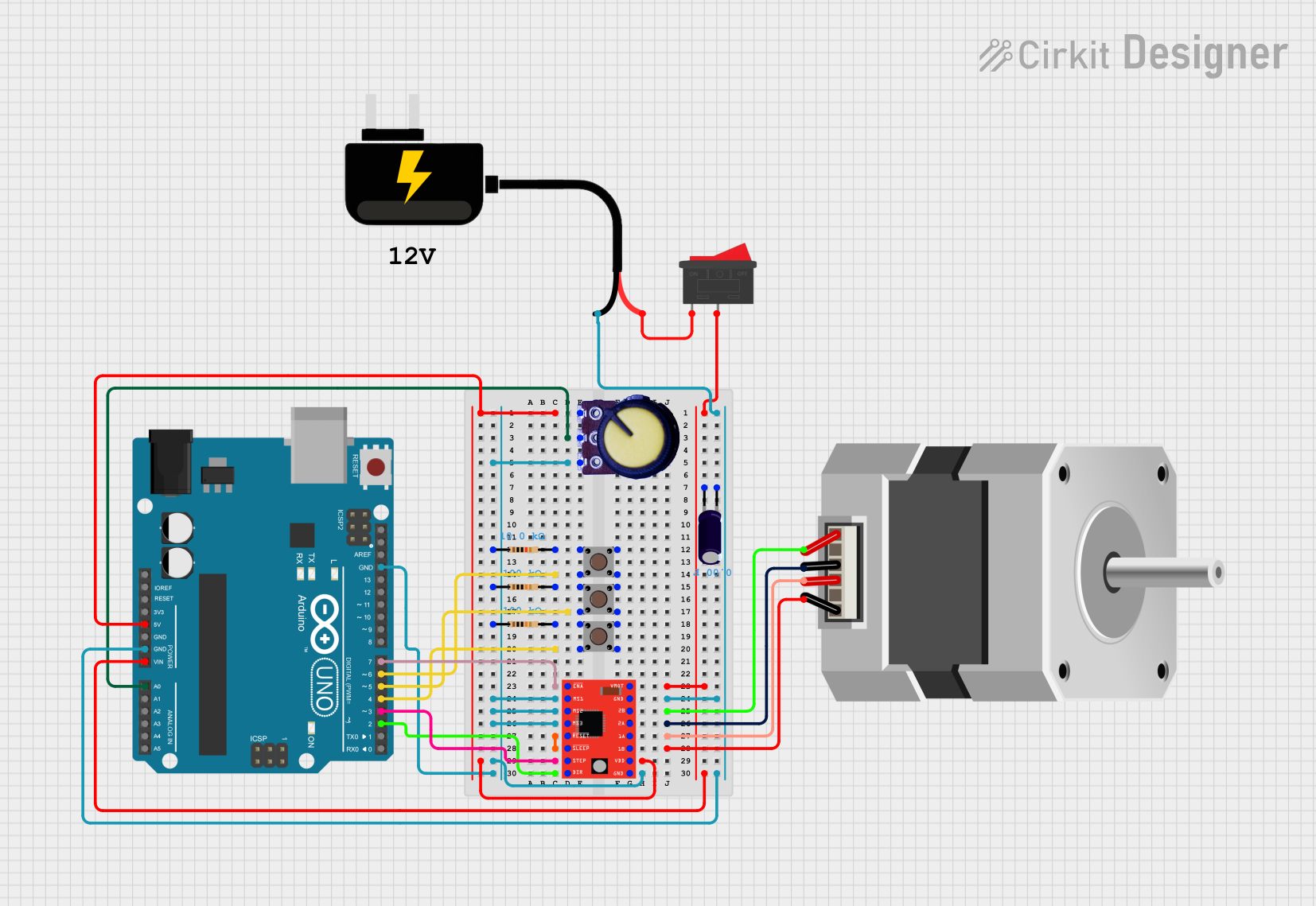
This circuit is designed to control a NEMA23 stepper motor using an A4988 Stepper Motor Driver, interfaced with an Arduino UNO microcontroller. The circuit includes various resistors and pushbuttons for input control, a potentiometer for adjustable parameters, and a DC power source for supplying power. The A4988 driver allows for precise control of the stepper motor through digital signals provided by the Arduino UNO.
Component List
Microcontroller
- Arduino UNO: A microcontroller board based on the ATmega328P, featuring digital and analog I/O pins.
Motor Driver
- A4988 Stepper Motor Driver (Red): A complete microstepping motor driver with built-in translator for easy operation.
Motors
- NEMA23 Stepper Motor: A stepper motor with four wires, suitable for being driven by the A4988 driver.
Passive Components
- Resistors: Three resistors with different resistance values (10k Ohms, 100k Ohms, 100k Ohms) used for various functions in the circuit.
- Electrolytic Capacitor: A capacitor used for voltage smoothing on the motor power supply.
Input Devices
- Pushbuttons: Three pushbuttons used for providing user inputs to the microcontroller.
- Potentiometer: A variable resistor used to provide an adjustable voltage input to the microcontroller.
Power Supply
- DC Source 9V: A direct current power source providing 9V.
- Rocker Switch: A switch used to control the power supply to the circuit.
Wiring Details
Arduino UNO
- 5V pin connected to the VDD pin of the A4988 and the GND pin of the Potentiometer.
- GND pin connected to the GND pins of the A4988, Potentiometer, and the negative side of the Electrolytic Capacitor.
- A0 pin connected to the Output pin of the Potentiometer.
- D2-D7 pins connected to various control pins of the A4988 and the input pins of the Pushbuttons.
A4988 Stepper Motor Driver (Red)
- ENABLE, STEP, DIR connected to the corresponding control pins on the Arduino UNO.
- MS1, MS2, MS3 connected together and to the VCC pin of the Potentiometer through resistors.
- RESET and SLEEP pins shorted together.
- VMOT connected to the positive side of the Electrolytic Capacitor and through the Rocker Switch to the VCC of the DC Source 9V.
- GND connected to the negative side of the Electrolytic Capacitor and the GND of the DC Source 9V.
- 1A, 1B, 2A, 2B connected to the corresponding pins on the NEMA23 stepper motor.
NEMA23 Stepper Motor
- A, B, C, D pins connected to the corresponding 2B, 2A, 1A, 1B pins on the A4988 Stepper Motor Driver.
Potentiometer
- GND pin connected to the GND of the Arduino UNO.
- Output pin connected to the A0 pin of the Arduino UNO.
- VCC pin connected through resistors to the MS1, MS2, MS3 pins of the A4988.
Pushbuttons
- Pin 1 (in) of each pushbutton connected to the D4, D5, D6 pins of the Arduino UNO.
- Pin 3 (out) of each pushbutton connected through a resistor to the GND.
Electrolytic Capacitor
- Positive side connected to the VMOT of the A4988 and through the Rocker Switch to the VCC of the DC Source 9V.
- Negative side connected to the GND of the A4988 and the GND of the DC Source 9V.
DC Source 9V
- VCC pin connected through the Rocker Switch to the VMOT of the A4988 and the positive side of the Electrolytic Capacitor.
- GND pin connected to the GND of the A4988 and the negative side of the Electrolytic Capacitor.
Rocker Switch
- Pin 1 connected to the VCC of the DC Source 9V.
- Pin 2 connected to the VMOT of the A4988 and the positive side of the Electrolytic Capacitor.
Documented Code
void setup() {
  // put your setup code here, to run once:

}

void loop() {
  // put your main code here, to run repeatedly:

}
The provided code is a template with empty setup() and loop() functions, which are the standard structure for Arduino sketches. The setup() function is intended to contain initialization code that runs once when the program starts, and the loop() function should contain the main logic that runs continuously. Additional code is required to control the A4988 stepper motor driver and read inputs from the potentiometer and pushbuttons.