
Arduino-Controlled Gas Detection System with Relay-Triggered Exhaust Fan and Alert Buzzer
View and Edit Project In Cirkit Designer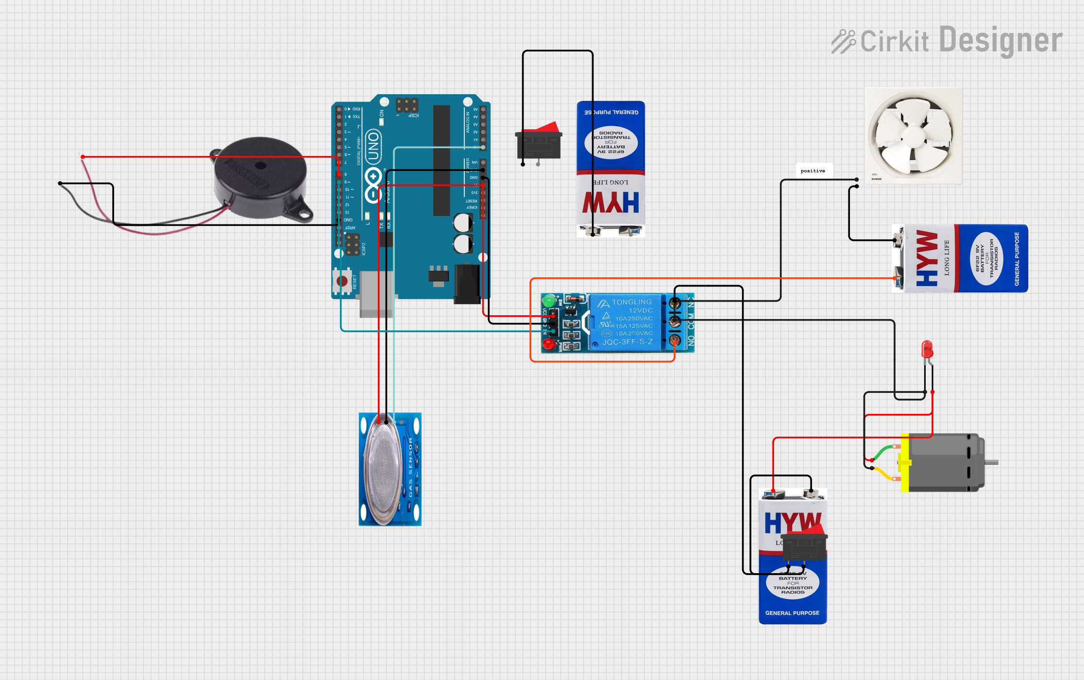
Circuit Documentation
Summary
This circuit is designed to interface various components with an Arduino UNO microcontroller. The circuit includes a buzzer, an MQ-5 gas sensor, a 12V single-channel relay, an exhaust fan, three 9V batteries, two rocker switches, a DC motor, and a red LED. The Arduino UNO controls the buzzer, reads the digital output from the MQ-5 sensor, and drives the relay to control the power to the exhaust fan, DC motor, and LED. The batteries provide power to the relay and the components connected to it. The rocker switches are used to control the power flow from the batteries.
Component List
- Buzzer: A simple piezoelectric buzzer for audible alerts.
- Arduino UNO: A microcontroller board based on the ATmega328P, with a variety of digital and analog I/O pins.
- MQ-5 Gas Sensor: A gas sensor for detecting LPG, natural gas, and coal gas.
- 12V Single Channel Relay: An electromechanical switch that allows the Arduino to control higher power circuits.
- Exhaust Fan 12": A fan used to ventilate an area by expelling air.
- 9V Battery: Three batteries provide power to the circuit.
- Rocker Switch: Two switches used to control the connection of the batteries to the circuit.
- DC Motor: A motor that converts electrical energy into mechanical rotation.
- LED (Red, Two Pin): A red light-emitting diode used as an indicator.
Wiring Details
Buzzer
- POSITIVE: Connected to Arduino UNO pin D8.
- NEGATIVE: Connected to Arduino UNO GND.
Arduino UNO
- 5V: Powers the MQ-5 sensor and the 12V relay.
- GND: Common ground for Buzzer, MQ-5 sensor, and 12V relay.
- A0: Reads the digital output from the MQ-5 sensor.
- D8: Drives the buzzer.
- D9: Controls the relay input.
MQ-5 Gas Sensor
- VCC: Powered by Arduino UNO 5V.
- GND: Connected to Arduino UNO GND.
- Digi Out: Connected to Arduino UNO A0.
12V Single Channel Relay
- VCC: Powered by Arduino UNO 5V.
- GND: Connected to Arduino UNO GND.
- IN: Controlled by Arduino UNO D9.
- NC: Connected to one terminal of Rocker Switch.
- COM: Connected to DC Motor pin 2, Exhaust Fan Live, and LED cathode.
- NO: Connected to the positive terminal of a 9V battery.
Exhaust Fan 12"
- Live: Connected to relay COM.
- Neutral: Connected to the negative terminal of a 9V battery.
9V Batteries
- Battery 1: Positive terminal connected to relay NO, negative terminal connected to Exhaust Fan Neutral.
- Battery 2: Positive terminal connected to DC Motor pin 1 and LED anode, negative terminal connected to Rocker Switch 1.
- Battery 3: Not directly connected in the net list provided.
Rocker Switches
- Switch 1: Terminal 1 connected to the negative terminal of Battery 2, Terminal 2 connected to the positive terminal of Battery 3.
- Switch 2: Terminal 1 connected to the negative terminal of Battery 3, Terminal 2 connected to relay NC.
DC Motor
- Pin 1: Connected to the positive terminal of Battery 2.
- Pin 2: Connected to relay COM.
LED (Red, Two Pin)
- Anode: Connected to the positive terminal of Battery 2.
- Cathode: Connected to relay COM.
Documented Code
Arduino UNO Code (sketch.ino)
void setup() {
  // put your setup code here, to run once:

}

void loop() {
  // put your main code here, to run repeatedly:

}
Note: The provided code for the Arduino UNO is a template with empty setup and loop functions. This code needs to be completed with the logic for reading the sensor, driving the buzzer, and controlling the relay based on the sensor's output.
Additional Documentation (documentation.txt)
No additional documentation code was provided.