
Arduino UNO Based Environmental Monitoring System with Solar Charging
View and Edit Project In Cirkit Designer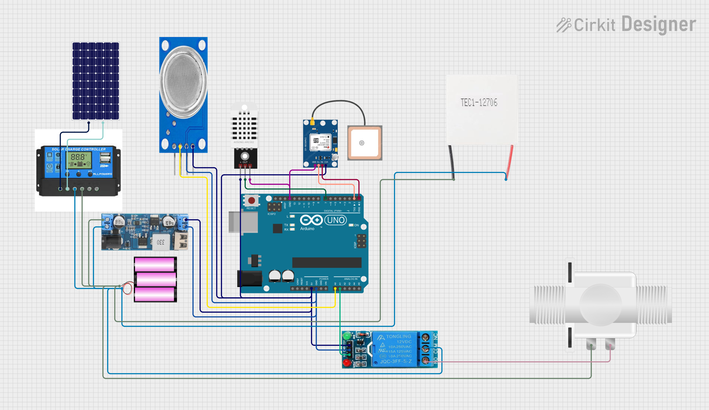
Circuit Documentation
Summary
This circuit integrates various components to perform multiple functions. It includes an Arduino UNO as the central microcontroller, interfacing with sensors like the DHT22 for temperature and humidity readings and the MQ135 for air quality monitoring. A GPS NEO 6M module provides location tracking capabilities. Power management is handled by a 12V battery, a solar panel, and a charge controller, with a 12v to 5v step-down power converter to supply the necessary voltage levels to the components. A Peltier module is used for heating or cooling applications, and a plastic solenoid valve is controlled via a 12V single-channel relay for fluid flow control.
Component List
- Arduino UNO: A microcontroller board based on the ATmega328P, featuring digital and analog I/O pins.
- DHT22: A sensor for measuring temperature and humidity.
- MQ135: An air quality sensor for detecting a wide range of gases, including NH3, NOx, alcohol, benzene, smoke, and CO2.
- GPS NEO 6M: A GPS module for satellite navigation.
- Peltier Module: A thermoelectric device that can heat or cool depending on the direction of the electrical current.
- Plastic Solenoid Valve: An electrically-controlled valve used for controlling the flow of liquids.
- Battery 12V: A 12-volt battery providing the power source for the circuit.
- Solar Panel: A photovoltaic panel that converts sunlight into electrical energy.
- Charge Controller: A device that regulates the voltage and current coming from the solar panels going to the battery.
- 12V to 5V Step Down Power Converter: A DC-DC converter that steps down the voltage from 12V to 5V.
- 12V Single Channel Relay: An electrically operated switch that allows you to control a high power circuit with a low power signal.
Wiring Details
Arduino UNO
- 5V: Connected to the 5V output from the step-down power converter, MQ135 VCC, GPS NEO 6M VCC, and DHT22 +.
- GND: Common ground with the step-down power converter, MQ135 GND, GPS NEO 6M GND, and DHT22 -.
- A0: Connected to MQ135 A0.
- A1: Connected to the IN pin of the 12V single-channel relay.
- D7: Connected to the Out pin of the DHT22.
- D1 (TX): Connected to the RX pin of the GPS NEO 6M.
- D0 (RX): Connected to the TX pin of the GPS NEO 6M.
DHT22
- +: Connected to the 5V supply from the Arduino UNO.
- Out: Connected to the D7 pin on the Arduino UNO.
- -: Connected to the common ground.
MQ135
- VCC: Connected to the 5V supply from the step-down power converter.
- GND: Connected to the common ground.
- A0: Connected to the A0 pin on the Arduino UNO.
GPS NEO 6M
- VCC: Connected to the 5V supply from the step-down power converter.
- RX: Connected to the D0 (RX) pin on the Arduino UNO.
- TX: Connected to the D1 (TX) pin on the Arduino UNO.
- GND: Connected to the common ground.
Peltier Module
- Positive: Connected to the VIN+ of the step-down power converter and the Battery Positive of the charge controller.
- Negative: Connected to the VIN- of the step-down power converter and the Battery Negative of the charge controller.
Plastic Solenoid Valve
- Pin1: Connected to the Battery Negative of the charge controller.
- Pin2: Connected to the NO pin of the 12V single-channel relay.
Battery 12V
- +: Connected to the Battery Positive of the charge controller and the VIN+ of the step-down power converter.
- -: Connected to the Battery Negative of the charge controller and the VIN- of the step-down power converter.
Solar Panel
- +: Connected to the Solar Positive of the charge controller.
- -: Connected to the Solar Negative of the charge controller.
Charge Controller
- Solar Positive/Negative: Connected to the corresponding pins on the solar panel.
- Battery Positive/Negative: Connected to the corresponding pins on the battery and the Peltier Module.
- Load Positive/Negative: Not explicitly connected in the provided net list.
12V to 5V Step Down Power Converter
- VIN 9v-36v: Not explicitly connected in the provided net list.
- VIN+: Connected to the Battery Positive and the Peltier Module Positive.
- VIN-: Connected to the Battery Negative and the Peltier Module Negative.
- 5V OUTPUT: Connected to the 5V supply line for the Arduino UNO, MQ135, GPS NEO 6M, and DHT22.
12V Single Channel Relay
- VCC: Connected to the 5V supply from the step-down power converter.
- GND: Connected to the common ground.
- IN: Connected to the A1 pin on the Arduino UNO.
- COM: Connected to the Battery Positive.
- NO: Connected to the Pin2 of the Plastic Solenoid Valve.
Documented Code
Arduino UNO Code (sketch.ino)
void setup() {
  // put your setup code here, to run once:

}

void loop() {
  // put your main code here, to run repeatedly:

}
This is a template for the Arduino UNO code. The setup() function is called once when the microcontroller is reset or powered on, and it is used to initialize the environment. The loop() function is called repeatedly and contains the main logic of the program. The actual implementation details would be added to these functions based on the specific requirements of the circuit's operation.