
ESP32 and INA3221-Based Smart Power Monitoring System with Bluetooth and Environmental Sensing
View and Edit Project In Cirkit Designer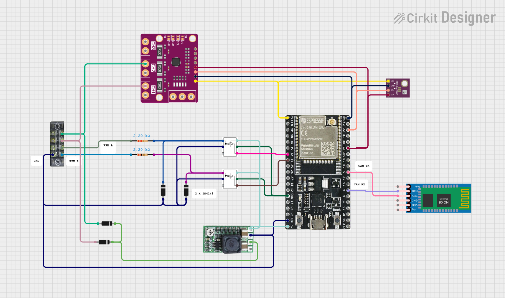
Circuit Documentation
Summary
This document provides a detailed overview of a circuit that includes various components such as power monitors, microcontrollers, sensors, and communication modules. The circuit is designed to monitor power, communicate wirelessly, and interface with sensors. The ESP32 microcontroller is the central unit that controls and communicates with other components.
Component List
INA 3221 Power Monitor
- Description: Power monitor for measuring voltage and current.
- Pins: TC, WAR, CRI, PV, SDA, SCL, GND, VS, VPU, POW, GND CH1, CH1, GND CH2, CH2, GND CH3, CH3
ESP32-WROOM-32UE
- Description: Wi-Fi and Bluetooth microcontroller.
- Pins: 3v3, EN, VP, VN, 34, 35, 32, 33, 25, 26, 27, 14, 12, GND, 13, D2, D3, 5V, 23, 22, TX, RX, 21, 19, 18, 5, 17, 16, 4, 0, 2, 15, D1, D0, CKL
H11L1
- Description: Optocoupler for isolating different sections of the circuit.
- Pins: ANODE, CATODE, VCC, GROUND, VO
Terminal Block (8-pin)
- Description: Terminal block for connecting external wires.
- Pins: 1, 2, 3, 4, 5, 6, 7, 8
Resistor (2200 Ohms)
- Description: Resistor for current limiting.
- Pins: pin1, pin2
Diode
- Description: Diode for controlling the direction of current flow.
- Pins: cathode, anode
C Step-Down Module
- Description: Step-down voltage regulator.
- Pins: VO+, GND, IN+, EN
BME/BMP280
- Description: Environmental sensor for measuring temperature, pressure, and humidity.
- Pins: GND, SCL, SDA, VIN
HC-05 Bluetooth Module
- Description: Bluetooth module for wireless communication.
- Pins: Key, VCC, TXD, RXD, State, GND
Wiring Details
INA 3221 Power Monitor
- SDA: Connected to ESP32-WROOM-32UE (pin 21) and BME/BMP280 (pin SDA)
- SCL: Connected to ESP32-WROOM-32UE (pin 22) and BME/BMP280 (pin SCL)
- GND: Connected to ESP32-WROOM-32UE (pin GND) and BME/BMP280 (pin GND)
- VS: Connected to ESP32-WROOM-32UE (pin 3v3) and BME/BMP280 (pin VIN)
- CH1: Connected to Terminal Block (pin 6) and Diode (anode)
- CH2: Connected to Terminal Block (pin 8) and Diode (anode)
ESP32-WROOM-32UE
- Pin 21: Connected to INA 3221 Power Monitor (pin SDA) and BME/BMP280 (pin SDA)
- Pin 22: Connected to INA 3221 Power Monitor (pin SCL) and BME/BMP280 (pin SCL)
- Pin GND: Connected to INA 3221 Power Monitor (pin GND), BME/BMP280 (pin GND), H11L1 (pin GROUND), Terminal Block (pin 1), and C Step-Down Module (pin GND)
- Pin 3v3: Connected to INA 3221 Power Monitor (pin VS) and BME/BMP280 (pin VIN)
- Pin 32: Connected to H11L1 (pin VO)
- Pin 33: Connected to H11L1 (pin VO)
- Pin 5: Connected to HC-05 Bluetooth Module (pin TXD)
- Pin 4: Connected to HC-05 Bluetooth Module (pin RXD)
- Pin 5V: Connected to H11L1 (pin VCC) and C Step-Down Module (pin VO+)
H11L1
- Pin VO: Connected to ESP32-WROOM-32UE (pin 32)
- Pin VO: Connected to ESP32-WROOM-32UE (pin 33)
- Pin GROUND: Connected to ESP32-WROOM-32UE (pin GND)
- Pin VCC: Connected to ESP32-WROOM-32UE (pin 5V) and C Step-Down Module (pin VO+)
- Pin ANODE: Connected to Resistor (pin2) and Diode (cathode)
Terminal Block (8-pin)
- Pin 6: Connected to INA 3221 Power Monitor (pin CH1) and Diode (anode)
- Pin 8: Connected to INA 3221 Power Monitor (pin CH2) and Diode (anode)
- Pin 1: Connected to Diode (anode), H11L1 (pin CATODE), and ESP32-WROOM-32UE (pin GND)
- Pin 2: Connected to Resistor (pin1)
Resistor (2200 Ohms)
- Pin1: Connected to Terminal Block (pin 2)
- Pin2: Connected to Diode (cathode) and H11L1 (pin ANODE)
Diode
- Anode: Connected to Terminal Block (pin 6) and INA 3221 Power Monitor (pin CH1)
- Anode: Connected to Terminal Block (pin 8) and INA 3221 Power Monitor (pin CH2)
- Anode: Connected to Terminal Block (pin 1), H11L1 (pin CATODE), and ESP32-WROOM-32UE (pin GND)
- Cathode: Connected to Resistor (pin2) and H11L1 (pin ANODE)
- Cathode: Connected to C Step-Down Module (pin IN+)
C Step-Down Module
- Pin VO+: Connected to ESP32-WROOM-32UE (pin 5V) and H11L1 (pin VCC)
- Pin GND: Connected to ESP32-WROOM-32UE (pin GND)
- Pin IN+: Connected to Diode (cathode)
BME/BMP280
- Pin SDA: Connected to ESP32-WROOM-32UE (pin 21) and INA 3221 Power Monitor (pin SDA)
- Pin SCL: Connected to ESP32-WROOM-32UE (pin 22) and INA 3221 Power Monitor (pin SCL)
- Pin GND: Connected to ESP32-WROOM-32UE (pin GND) and INA 3221 Power Monitor (pin GND)
- Pin VIN: Connected to ESP32-WROOM-32UE (pin 3v3) and INA 3221 Power Monitor (pin VS)
HC-05 Bluetooth Module
- Pin TXD: Connected to ESP32-WROOM-32UE (pin 5)
- Pin RXD: Connected to ESP32-WROOM-32UE (pin 4)
Documented Code
ESP32-WROOM-32UE Code
void setup() {
  // put your setup code here, to run once:

}

void loop() {
  // put your main code here, to run repeatedly:

}
This concludes the documentation for the circuit. Each component and its connections have been detailed, along with the code for the ESP32 microcontroller.