
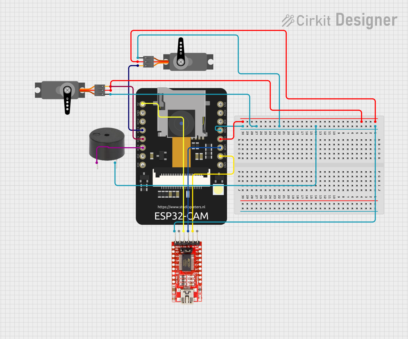
Circuit Documentation
Summary
This document provides a detailed overview of a circuit involving an ESP32 CAM, an FTDI Programmer, a buzzer, and two servos. The ESP32 CAM serves as the central microcontroller, interfacing with the FTDI Programmer for programming and communication, controlling a buzzer for audio signals, and managing two servos for mechanical movements.
Component List
ESP32 CAM
- Description: A microcontroller with integrated Wi-Fi and Bluetooth, suitable for IoT applications.
- Pins: 5V, GND, GPIO12, GPIO13, GPIO15, GPIO14, GPIO2, GPIO4, 3.3V, GPIO16, GPIO0, 3.3V / 5V / P_OUT, GPIO3 / RX, GPIO1 / TX
FTDI Programmer
- Description: A USB-to-serial adapter used for programming and communication with microcontrollers.
- Pins: DTR, RX, TX, VCC, CTS, GND
Buzzer
- Description: An audio signaling device.
- Pins: PIN, GND
Servo (1)
- Description: A motor used for precise control of angular position.
- Pins: GND, VCC, PWM
Servo (2)
- Description: Another motor used for precise control of angular position.
- Pins: GND, VCC, PWM
Wiring Details
ESP32 CAM
- 5V: Connected to FTDI Programmer VCC
- GND: Connected to FTDI Programmer GND, Buzzer GND, Servo (1) GND, Servo (2) GND
- GPIO13: Connected to Servo (1) PWM
- GPIO15: Connected to Servo (2) PWM
- GPIO14: Connected to Buzzer PIN
- 3.3V / 5V / P_OUT: Connected to Servo (1) VCC, Servo (2) VCC
- GPIO3 / RX: Connected to FTDI Programmer TX
- GPIO1 / TX: Connected to FTDI Programmer RX
FTDI Programmer
- VCC: Connected to ESP32 CAM 5V
- GND: Connected to ESP32 CAM GND
- TX: Connected to ESP32 CAM GPIO3 / RX
- RX: Connected to ESP32 CAM GPIO1 / TX
Buzzer
- PIN: Connected to ESP32 CAM GPIO14
- GND: Connected to ESP32 CAM GND
Servo (1)
- GND: Connected to ESP32 CAM GND
- VCC: Connected to ESP32 CAM 3.3V / 5V / P_OUT
- PWM: Connected to ESP32 CAM GPIO13
Servo (2)
- GND: Connected to ESP32 CAM GND
- VCC: Connected to ESP32 CAM 3.3V / 5V / P_OUT
- PWM: Connected to ESP32 CAM GPIO15
Code
No code is provided for this circuit.
This document provides a comprehensive overview of the circuit, including a summary, detailed component list, wiring details, and code documentation.