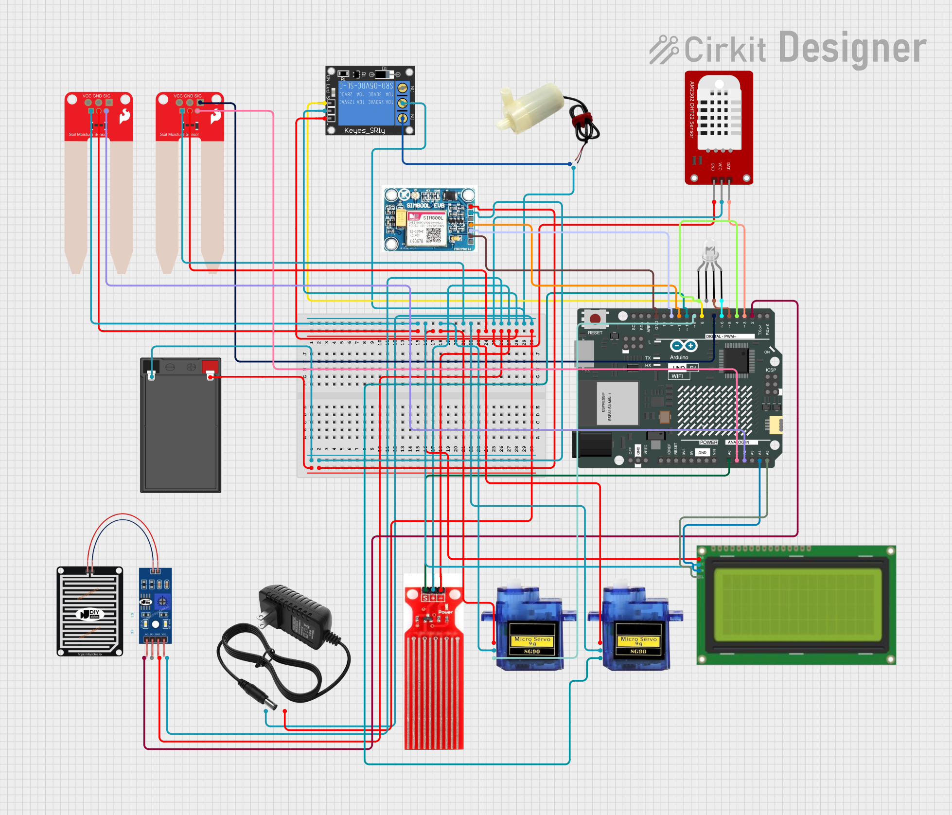
Arduino UNO R4 WiFi-Based Smart Irrigation and Environmental Monitoring System

Circuit Documentation
Summary
This circuit is designed to interface various sensors and actuators with an Arduino UNO R4 WiFi microcontroller. The sensors include a rain sensor, two soil moisture sensors, a water sensor, and a DHT22 temperature and humidity sensor. Actuators in the circuit include a mini water pump, two micro servos, and an RGB LED. Additionally, the circuit incorporates a SIM 800L GSM module for cellular communication, a relay for controlling high-power devices, and an LCD for displaying information. The circuit is powered by a 12V power supply and a battery for the GSM module.
Component List
Arduino UNO R4 WiFi
- Microcontroller board with WiFi capability.
- Pins: OFF, GND, VRTC, IIC0_SCL, IIC0_SDA, 3V3, GPIO 41, GPIO 0, GPIO 42, GPIO 43, GPIO 44, BOOT, IOREF, RESET, 5V, VIN, A0-A5, RSPCKA, CIPO, COPI, D0/RX, D1/TX, D2-D13, AREF, SDA, SCL.
Rain Sensor
- Detects rainwater and provides analog and digital outputs.
- Pins: AO, DO, GRD, VCC.
5V Mini Water Pump
- A small pump for moving water.
- Pins: Positive pin, Negative pin.
DHT22
- A sensor for measuring temperature and humidity.
- Pins: GND, VCC, DAT.
LED: Four Pin
- An RGB LED with a common anode.
- Pins: Red cathode, Common anode, Green cathode, Blue cathode.
SIM 800L V2.0 GSM
- GSM module for cellular communication.
- Pins: SIM_TXD, VDD, SIM.RXD, 5V/4V, GND, RST.
SparkFun Soil Moisture Sensor
- Measures the moisture level in the soil.
- Pins: VCC, GND, SIG.
Lcd 20x4 i2c
- An LCD display with I2C interface.
- Pins: GND, 5V, SCA, SCL.
Micro Servo 9G
- A small servo motor for precise control.
- Pins: GND, +5V, PWM.
Water Sensor
- Detects the presence of water.
- Pins: Signal, VCC, GND.
1-Channel Relay (5V 10A)
- Controls high-power devices.
- Pins: NC, Signal, C, Power, NO, Ground.
12V Power Supply
- Provides power to the circuit.
- Pins: +, -.
Battery
- Provides backup power to the GSM module.
- Pins: -, +.
Wiring Details
Arduino UNO R4 WiFi
- A0 connected to Water Sensor Signal
- A1 connected to SparkFun Soil Moisture Sensor SIG
- A2 connected to SparkFun Soil Moisture Sensor SIG
- A4 connected to Lcd 20x4 i2c SCA
- A5 connected to Lcd 20x4 i2c SCL
- D2 connected to RAIN SENSOR AO
- D3 connected to DHT22 DAT
- D4 connected to LED: Four Pin Red cathode
- D5 connected to LED: Four Pin Green cathode
- D6 connected to LED: Four Pin Blue cathode
- D7 connected to SparkFun Soil Moisture Sensor SIG
- D8 connected to 1-Channel Relay Signal
- D9 connected to Micro Servo 9G PWM
- D10 connected to Micro Servo 9G PWM
- D11 connected to SIM 800L V2.0 GSM SIM_TXD
- D12 connected to SIM 800L V2.0 GSM SIM.RXD
- GND connected to various GND pins on other components
Rain Sensor
- AO connected to Arduino UNO R4 WiFi D2
- GRD connected to common ground
- VCC connected to common VCC
5V Mini Water Pump
- Negative pin connected to 1-Channel Relay NO
- Positive pin connected to common VCC
DHT22
- DAT connected to Arduino UNO R4 WiFi D3
- GND connected to common ground
- VCC connected to common VCC
LED: Four Pin
- Red cathode connected to Arduino UNO R4 WiFi D4
- Green cathode connected to Arduino UNO R4 WiFi D5
- Blue cathode connected to Arduino UNO R4 WiFi D6
- Common anode connected to common VCC
SIM 800L V2.0 GSM
- SIM_TXD connected to Arduino UNO R4 WiFi D11
- SIM.RXD connected to Arduino UNO R4 WiFi D12
- GND connected to common ground and battery -
- 5V/4V connected to battery +
SparkFun Soil Moisture Sensor
- SIG connected to Arduino UNO R4 WiFi A1, A2, and D7
- GND connected to common ground
- VCC connected to common VCC
Lcd 20x4 i2c
- SCA connected to Arduino UNO R4 WiFi A4
- SCL connected to Arduino UNO R4 WiFi A5
- GND connected to common ground
- 5v connected to common VCC
Micro Servo 9G
- PWM connected to Arduino UNO R4 WiFi D9 and D10
- GND connected to common ground
- +5V connected to common VCC
Water Sensor
- Signal connected to Arduino UNO R4 WiFi A0
- GND connected to common ground
- VCC connected to common VCC
1-Channel Relay (5V 10A)
- Signal connected to Arduino UNO R4 WiFi D8
- C connected to common VCC
- NO connected to 5V Mini Water Pump Positive pin
- Ground connected to common ground
- Power connected to common VCC
12V Power Supply
- connected to common VCC
- connected to common ground
Battery
- connected to SIM 800L V2.0 GSM 5V/4V
- connected to SIM 800L V2.0 GSM GND
Documented Code
sketch.ino
void setup() {
  // put your setup code here, to run once:

}

void loop() {
  // put your main code here, to run repeatedly:

}
documentation.txt
The code for the microcontroller is currently a template with empty setup and loop functions. The setup function is intended to initialize the system (e.g., pin modes, serial communication, etc.), and the loop function will contain the main logic that runs continuously. Further implementation is required to control and read from the connected components based on the circuit design.