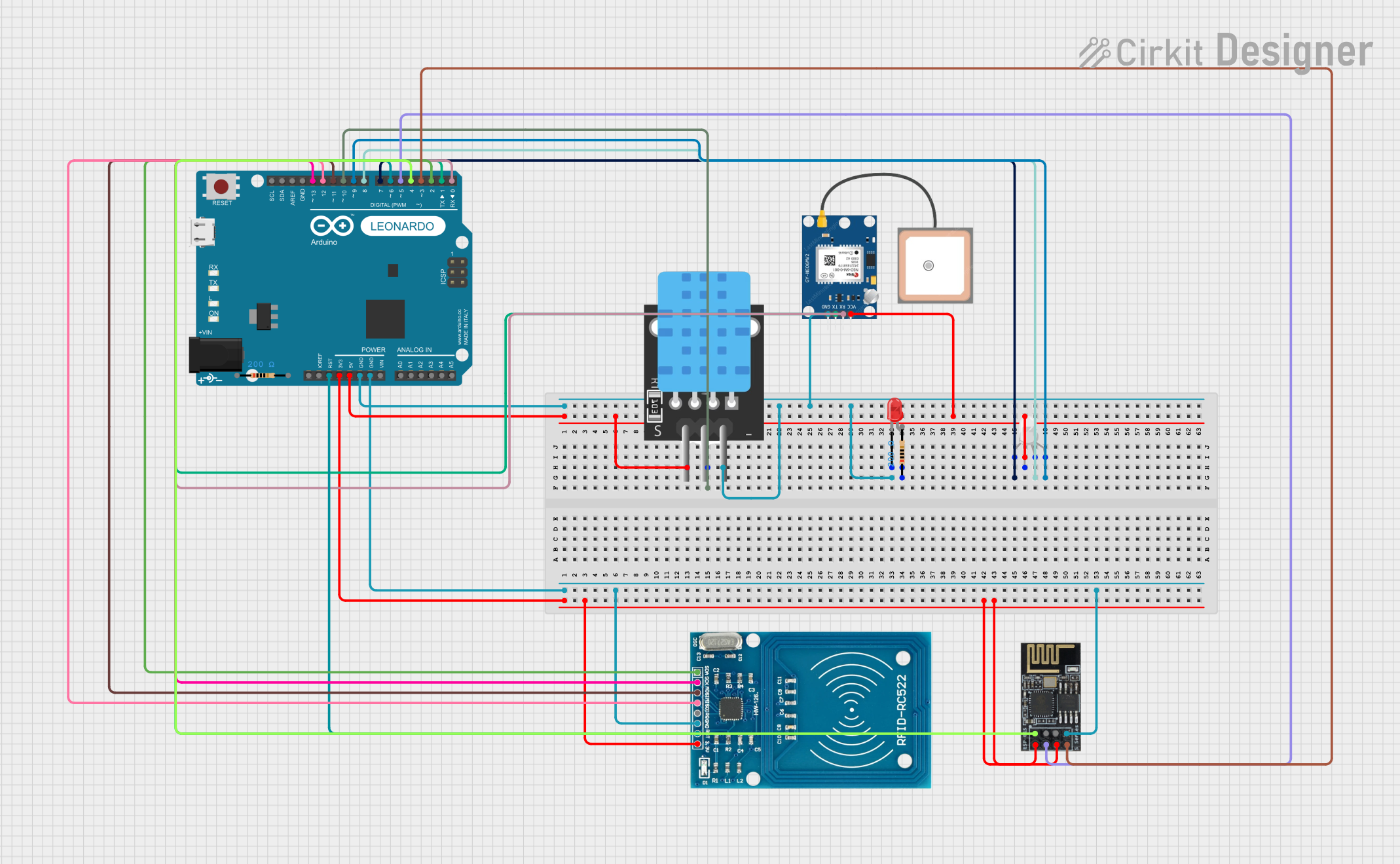
Arduino Leonardo-based IoT Connectivity Hub with GPS, RFID, and Temperature Sensing

Circuit Documentation
Summary
The circuit in question is a multifunctional embedded system that integrates various modules with an Arduino Leonardo microcontroller. The system includes a GPS module (NEO 6M) for location tracking, a Wi-Fi module (ESP8266-01) for wireless connectivity, an RFID reader (RC522) for contactless communication, temperature sensing capabilities (TEMP), and visual indicators (LEDs). The Arduino Leonardo serves as the central processing unit, interfacing with each module and sensor to perform specific tasks as programmed. The circuit is powered by the Arduino's onboard voltage regulators, providing both 5V and 3.3V to the respective components.
Component List
GPS NEO 6M
- Description: A GPS module capable of providing geographical location data.
- Pins: VCC, RX, TX, GND
Wifi module ESP8266-01
- Description: A Wi-Fi module for enabling wireless communication.
- Pins: RX, GPIO0, GPIO2, GND, +3V3, Reset, CH-PD, TX
RFID-RC522
- Description: An RFID reader for reading RFID tags and cards.
- Pins: VCC (3.3V), RST, GND, IRQ, MISO, MOSI, SCK, SDA
LED: Two Pin (red)
- Description: A simple red LED for indication purposes.
- Pins: cathode, anode
TEMP
- Description: A temperature sensor for measuring ambient temperature.
- Pins: 5V, D3, GND
RGB LED (Wokwi compatible)
- Description: An RGB LED capable of displaying multiple colors.
- Pins: R, COM, G, B
Arduino Leonardo (Rev3b)
- Description: A microcontroller board based on the ATmega32u4.
- Pins: D0/RX, D1/TX, D2/SDA, D3 PWM/SCL, D4/A6, D5 PWM, D6 PWM/A7, D7, n.c., IOREF, RESET, 3V3, 5V, GND, VIN, A0, A1, A2, A3, A4, A5, D8/A8, D9 PWM/A9, D10 PWM/A10, D11 PWM, D12/A11, D13 PWM, AREF, SDA, SCL
Resistor (200 Ohms)
- Description: A resistor with a resistance of 200 Ohms.
- Pins: pin1, pin2
Wiring Details
GPS NEO 6M
- VCC connected to Arduino Leonardo 5V
- RX connected to Arduino Leonardo D0/RX
- TX connected to Arduino Leonardo D1/TX
- GND connected to Arduino Leonardo GND
Wifi module ESP8266-01
- RX connected to Arduino Leonardo D4/A6
- GND connected to Arduino Leonardo GND
- +3V3 connected to Arduino Leonardo 3V3
- Reset connected to Arduino Leonardo D5 PWM
- CH-PD connected to Arduino Leonardo 3V3
- TX connected to Arduino Leonardo D3 PWM/SCL
RFID-RC522
- VCC (3.3V) connected to Arduino Leonardo 3V3
- RST connected to Arduino Leonardo RESET and D6 PWM/A7
- GND connected to Arduino Leonardo GND
- MISO connected to Arduino Leonardo D12/A11
- MOSI connected to Arduino Leonardo D11 PWM
- SCK connected to Arduino Leonardo D13 PWM
- SDA connected to Arduino Leonardo D2/SDA
LED: Two Pin (red)
- cathode connected to Arduino Leonardo GND
- anode connected to one pin of a 200 Ohms resistor
TEMP
- 5V connected to Arduino Leonardo 5V
- D3 connected to Arduino Leonardo D10 PWM/A10
- GND connected to Arduino Leonardo GND
RGB LED (Wokwi compatible)
- R connected to Arduino Leonardo D7
- COM connected to Arduino Leonardo 5V
- G connected to Arduino Leonardo D8/A8
- B connected to Arduino Leonardo D9 PWM/A9
Resistor (200 Ohms)
- One pin connected to the anode of the red LED
- The other pin is not connected in the provided net list
Documented Code
No code was provided for the microcontrollers in the circuit. The documentation of the code would typically include a description of the functionality implemented, setup and loop functions for Arduino sketches, and any functions or libraries used to interface with the components. Since no code is available, this section remains empty.