
Circuit Documentation
Summary
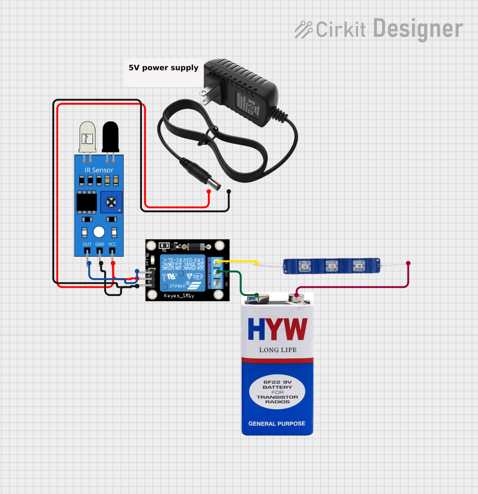
The circuit described in the provided inputs consists of a relay module, an infrared (IR) sensor, a 12V blue LED, a 12V power supply, and a 9V battery. The relay module is controlled by the output of the IR sensor. When the IR sensor detects an object, it activates the relay, which in turn powers the 12V blue LED. The 12V power supply provides power to the relay module and the IR sensor, while the 9V battery is connected to the common (COM) terminal of the relay and provides power to the LED when the relay is activated.
Component List
Relay Module 1 Channel
- Pins: S, 5V, GND, NC, COM, NO
- Description: A relay module capable of switching higher power loads using a low power signal from the IR sensor.
IR Sensor
- Pins: out, gnd, vcc
- Description: An infrared sensor used to detect the presence of an object and provide a signal to the relay module.
12V Blue LED
- Pins: GND, VCC
- Description: A blue LED that illuminates when powered by the 9V battery through the relay module.
12V Power Supply
- Pins: +, -
- Description: Provides the necessary 12V power to the relay module and the IR sensor.
9V Battery
- Pins: +, -
- Description: Provides power to the blue LED through the relay module when the relay is activated.
Comment
- Pins: N/A
- Description: This component is a placeholder and does not have a physical representation in the circuit.
Wiring Details
Relay Module 1 Channel
- S: Connected to the IR sensor output.
- 5V: Connected to the 12V power supply positive terminal.
- GND: Connected to the 12V power supply negative terminal.
- NC: Connected to the 12V blue LED VCC.
- COM: Connected to the 9V battery positive terminal.
- NO: Not connected in this circuit.
IR Sensor
- out: Connected to the Relay module S pin.
- gnd: Connected to the 12V power supply negative terminal.
- vcc: Connected to the 12V power supply positive terminal.
12V Blue LED
- GND: Connected to the 9V battery negative terminal.
- VCC: Connected to the Relay module NC pin.
12V Power Supply
- +: Connected to the Relay module 5V pin and the IR sensor vcc pin.
- -: Connected to the Relay module GND pin and the IR sensor gnd pin.
9V Battery
- +: Connected to the Relay module COM pin.
- -: Connected to the 12V blue LED GND pin.
Documented Code
No code has been provided for any microcontrollers in the circuit. Therefore, this section is not applicable for the current documentation.