
Circuit Documentation
Summary of the Circuit
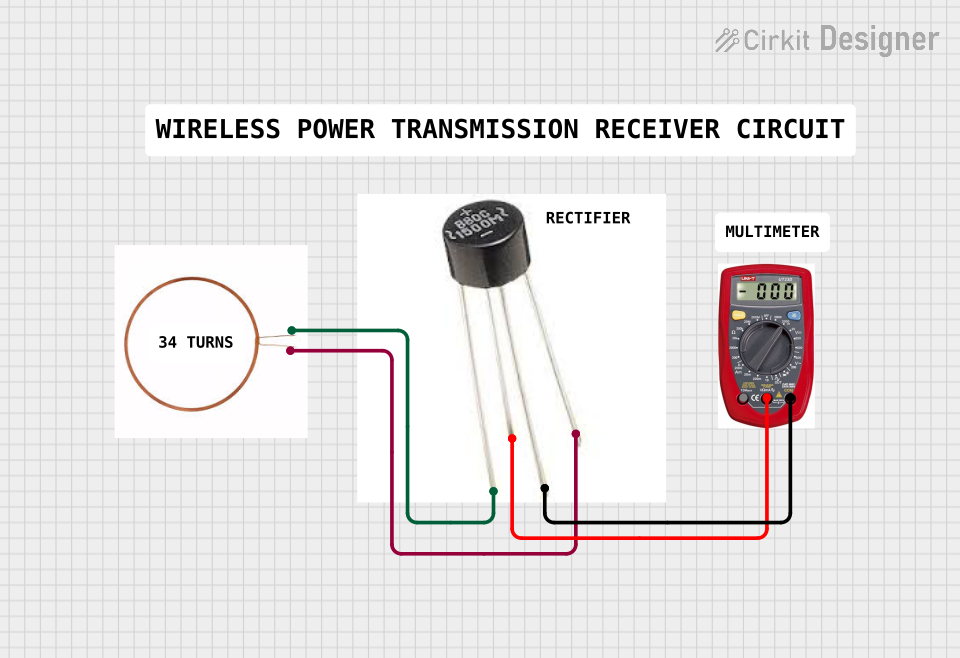
The circuit under consideration appears to be a simple test setup involving two copper coils and a multimeter. The purpose of the circuit is not explicitly stated, but based on the components and connections, it could be used to measure the electrical characteristics of the copper coils, such as resistance or inductance. There are no active electronic components like microcontrollers or integrated circuits, and no embedded code is provided as part of the circuit design.
Component List
Copper Coil 1
- Description: A copper coil with two terminals.
- Pins:
-ve,+ve
Copper Coil 2
- Description: Another copper coil, this one with four terminals.
- Pins:
pin1,pin 2,positive,negative
Multimeter
- Description: A device used to measure electrical properties such as voltage, current, and resistance.
- Pins:
COM,V,A
Wiring Details
Copper Coil 1
- -ve: Connected to
pin 2of Copper Coil 2. - +ve: Connected to
pin1of Copper Coil 2.
Copper Coil 2
- pin1: Connected to
+veof Copper Coil 1. - pin 2: Connected to
-veof Copper Coil 1. - positive: Connected to
Vof the Multimeter. - negative: Connected to
COMof the Multimeter.
Multimeter
- COM: Connected to
negativeof Copper Coil 2. - V: Connected to
positiveof Copper Coil 2. - A: Not connected in the current configuration.
Documented Code
No code has been provided for this circuit as there are no programmable components involved. Therefore, there is no embedded code to document.
This documentation provides an overview of the circuit components and their connections. It should be noted that the actual functionality and purpose of the circuit would require additional context which is not provided here.