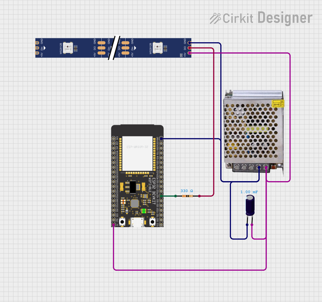
ESP32-Controlled WS2812 RGB LED Strip with Power Supply Stabilization

Circuit Documentation
Summary of the Circuit
This circuit is designed to power an ESP32 Wroom microcontroller and a WS2812 RGB LED strip from a 5V 5A power supply. The ESP32 Wroom is responsible for controlling the LED strip, and a resistor is used to protect the data input of the LED strip. An electrolytic capacitor is included to stabilize the power supply to the microcontroller and the LED strip.
Component List
ESP32 Wroom
- Description: A microcontroller with Wi-Fi and Bluetooth capabilities.
- Pins: 3.3V, Reset, GPIOs, Ground, 5V, and others for various functionalities.
WS2812 RGB LED Strip
- Description: An addressable LED strip that can be controlled for color and brightness on a per-LED basis.
- Pins: Data In (DIN), 5V, Ground (GND), Data Out (DO).
Power Supply 5V 5A
- Description: A power supply unit that converts AC voltage to 5V DC with a maximum current output of 5A.
- Pins: 220V AC input, Ground, 5V DC output.
Electrolytic Capacitor
- Description: A capacitor used for filtering and stabilizing the DC power supply.
- Value: 0.001 Farads (1 mF)
- Pins: Positive (+), Negative (-).
Resistor
- Description: A resistor used to limit current or voltage in a circuit.
- Value: 330 Ohms
- Pins: pin1, pin2.
Wiring Details
ESP32 Wroom
- 5V: Connected to the 5V output of the power supply.
- GND: Connected to the ground of the power supply.
- GPIO4: Connected to pin1 of the resistor.
WS2812 RGB LED Strip
- 5V: Connected to the 5V output of the power supply.
- GND: Connected to the ground of the power supply.
- DIN: Connected to pin2 of the resistor.
Power Supply 5V 5A
- 12V-24V Output (DC): Connected to the positive pin of the electrolytic capacitor, the 5V pin of the ESP32 Wroom, and the 5V pin of the WS2812 RGB LED strip.
- GND (DC): Connected to the negative pin of the electrolytic capacitor, the GND pin of the ESP32 Wroom, and the GND pin of the WS2812 RGB LED strip.
Electrolytic Capacitor
- Positive (+): Connected to the 5V output of the power supply.
- Negative (-): Connected to the ground of the power supply.
Resistor
- pin1: Connected to GPIO4 of the ESP32 Wroom.
- pin2: Connected to DIN of the WS2812 RGB LED strip.
Documented Code
There is no code provided for the microcontroller in this circuit. The ESP32 Wroom would typically be programmed to control the WS2812 RGB LED strip, handling color and brightness levels for each LED. The code would initialize the microcontroller's GPIOs, set up communication with the LED strip, and include functions to update the LED colors based on the desired patterns or inputs. Since no code is provided, this section will remain empty.