
Battery-Powered BLDC Motor and Servo Control System with FLYSKY Receiver
View and Edit Project In Cirkit Designer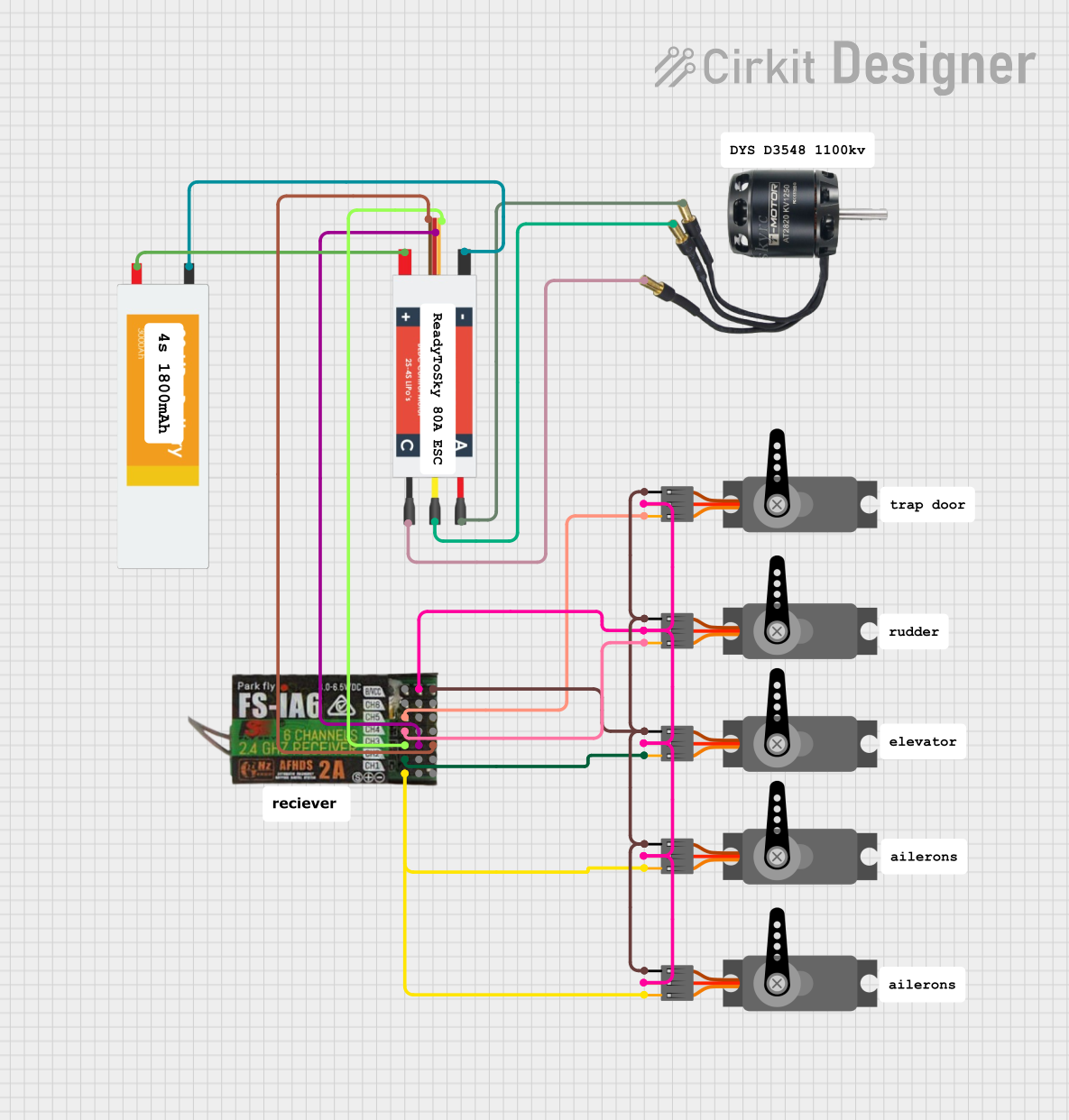
Circuit Documentation
Summary
This document provides a detailed overview of a circuit design involving a BLDC motor, multiple servos, an electronic speed controller (ESC), a FlySky FS-IA6 receiver, and a LiPo battery. The circuit is designed to control the motor and servos using the receiver, with power supplied by the LiPo battery.
Component List
BLDC Motor
- Pins: Wire A, Wire B, Wire C
- Description: A brushless DC motor used for precise control of rotational speed and torque.
Servo
- Pins: GND, VCC, PWM
- Description: A servo motor used for precise control of angular position.
Electronic Speed Controller (ESC)
- Pins: Battery VCC, Battery GND, Signal, 5v out, GND out, M1, M2, M3
- Description: An ESC used to control the speed of the BLDC motor.
FlySky FS-IA6
- Pins: CH1, 5V, GND, CH2, CH3, CH4, CH5, CH6, VCC
- Description: A receiver used to receive control signals from a remote transmitter.
LiPo Battery
- Pins: VCC, GND
- Description: A lithium polymer battery used to supply power to the circuit.
Wiring Details
BLDC Motor
- Wire A is connected to M3 of the Electronic Speed Controller (ESC).
- Wire B is connected to M2 of the Electronic Speed Controller (ESC).
- Wire C is connected to M1 of the Electronic Speed Controller (ESC).
Servo (Instance 1)
- GND is connected to GND of the FlySky FS-IA6.
- VCC is connected to 5V of the FlySky FS-IA6.
- PWM is connected to CH5 of the FlySky FS-IA6.
Servo (Instance 2)
- GND is connected to GND of the FlySky FS-IA6.
- VCC is connected to 5V of the FlySky FS-IA6.
- PWM is connected to CH4 of the FlySky FS-IA6.
Servo (Instance 3)
- GND is connected to GND of the FlySky FS-IA6.
- VCC is connected to 5V of the FlySky FS-IA6.
- PWM is connected to CH1 of the FlySky FS-IA6.
Servo (Instance 4)
- GND is connected to GND of the FlySky FS-IA6.
- VCC is connected to 5V of the FlySky FS-IA6.
- PWM is connected to CH1 of the FlySky FS-IA6.
Servo (Instance 5)
- GND is connected to GND of the FlySky FS-IA6.
- VCC is connected to 5V of the FlySky FS-IA6.
- PWM is connected to CH2 of the FlySky FS-IA6.
Electronic Speed Controller (ESC)
- Battery VCC is connected to VCC of the LiPo Battery.
- Battery GND is connected to GND of the LiPo Battery.
- Signal is connected to CH3 of the FlySky FS-IA6.
- 5v out is connected to 5V of the FlySky FS-IA6.
- GND out is connected to GND of the FlySky FS-IA6.
FlySky FS-IA6
- CH1 is connected to PWM of Servo (Instance 3) and Servo (Instance 4).
- CH2 is connected to PWM of Servo (Instance 5).
- CH3 is connected to Signal of the Electronic Speed Controller (ESC).
- CH4 is connected to PWM of Servo (Instance 2).
- CH5 is connected to PWM of Servo (Instance 1).
- 5V is connected to 5v out of the Electronic Speed Controller (ESC).
- GND is connected to GND out of the Electronic Speed Controller (ESC).
LiPo Battery
- VCC is connected to Battery VCC of the Electronic Speed Controller (ESC).
- GND is connected to Battery GND of the Electronic Speed Controller (ESC).
Code
There is no embedded code provided for this circuit.
This document provides a comprehensive overview of the circuit design, including a summary, component list, wiring details, and code documentation.