
ESP32-CAM Controlled Wi-Fi Robot with Dual Gearmotors and L298N Driver
View and Edit Project In Cirkit Designer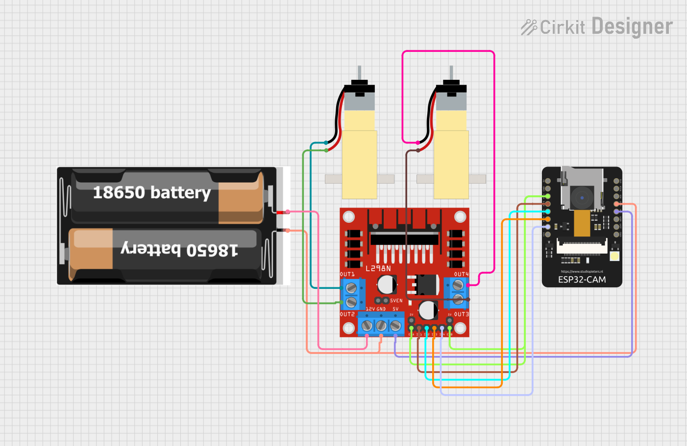
Circuit Documentation
Summary
This circuit is designed to control a pair of hobby gearmotors using an L298N DC motor driver, which is interfaced with an ESP32-CAM microcontroller. The ESP32-CAM also handles wireless communication and camera functionalities. The power source for the circuit is a pair of 18650 batteries. The ESP32-CAM receives commands over WiFi to control the motors' direction and speed, as well as to manage the camera's operation.
Component List
Hobby Gearmotor with 48:1 Gearbox
- Description: A DC motor with a gearbox to reduce speed and increase torque.
- Pins: 2 pins for motor connections.
ESP32 - CAM
- Description: A microcontroller with integrated Wi-Fi and a camera interface.
- Pins: Multiple GPIOs for interfacing with peripherals, power pins (3.3V, 5V, GND), and camera-specific pins.
2x 18650 Battery Holder
- Description: A battery holder for two 18650 batteries to provide power to the circuit.
- Pins: VCC and GND for power output.
L298N DC Motor Driver
- Description: A motor driver capable of driving two DC motors with direction and speed control.
- Pins: Motor output pins (OUT1-OUT4), power pins (12V, 5V, GND), control pins (ENA, ENB, IN1-IN4).
Wiring Details
Hobby Gearmotor 1
- Motor Pin 1: Connected to L298N OUT1
- Motor Pin 2: Connected to L298N OUT2
Hobby Gearmotor 2
- Motor Pin 1: Connected to L298N OUT4
- Motor Pin 2: Connected to L298N OUT3
ESP32 - CAM
- IO12: Connected to L298N ENA and ENB (motor enable)
- IO13: Connected to L298N IN1 (motor control)
- IO15: Connected to L298N IN2 (motor control)
- IO14: Connected to L298N IN3 (motor control)
- IO2: Connected to L298N IN4 (motor control)
- VCC: Connected to L298N 5V (power supply)
- GND: Connected to L298N GND and 18650 GND (common ground)
2x 18650 Battery Holder
- VCC: Connected to L298N 12V (power supply)
- GND: Connected to ESP32-CAM GND and L298N GND (common ground)
L298N DC Motor Driver
- OUT1-OUT4: Connected to the respective pins of the two Hobby Gearmotors
- 12V: Connected to 18650 VCC (power supply)
- GND: Connected to 18650 GND and ESP32-CAM GND (common ground)
- 5V: Connected to ESP32-CAM VCC (power supply)
- ENA, ENB: Connected to ESP32-CAM IO12 (motor enable)
- IN1-IN4: Connected to ESP32-CAM IO13, IO15, IO14, IO2 (motor control)
Documented Code
ESP32-CAM Code (sketch.ino)
#include <AsyncTCP.h>
#include "esp_camera.h"
#include <Arduino.h>
#include <WiFi.h>
#include <AsyncTCP.h>
#include <ESPAsyncWebServer.h>
#include <iostream>
#include <sstream>

// Motor pin structure and initialization
struct MOTOR_PINS {
  int pinEn;
  int pinIN1;
  int pinIN2;
};

std::vector<MOTOR_PINS> motorPins = {
  {12, 13, 15},  // RIGHT_MOTOR Pins (EnA, IN1, IN2)
  {12, 14, 2},   // LEFT_MOTOR  Pins (EnB, IN3, IN4)
};

#define LIGHT_PIN 4

// Movement directions
#define UP 1
#define DOWN 2
#define LEFT 3
#define RIGHT 4
#define STOP 0

// Motor identifiers
#define RIGHT_MOTOR 0
#define LEFT_MOTOR 1

// Motor directions
#define FORWARD 1
#define BACKWARD -1

// PWM settings
const int PWMFreq = 1000; /* 1 KHz */
const int PWMResolution = 8;
const int PWMSpeedChannel = 2;
const int PWMLightChannel = 3;

// Camera related constants
// (GPIO pin numbers and other camera settings)

// Wi-Fi credentials
const char* ssid     = "Cam_Car";
const char* password = "12345678";

// Web server and WebSocket setup
AsyncWebServer server(80);
AsyncWebSocket wsCamera("/Camera");
AsyncWebSocket wsCarInput("/CarInput");
uint32_t cameraClientId = 0;

// HTML content for the web interface
const char* htmlHomePage PROGMEM = R"HTMLHOMEPAGE(
<!DOCTYPE html>
<html>
  <!-- HTML content with JavaScript functions to handle WebSocket communication -->
</html>
)HTMLHOMEPAGE";

// Function to rotate the motor in a given direction
void rotateMotor(int motorNumber, int motorDirection) {
  // Implementation of motor rotation logic
}

// Function to move the car based on input value
void moveCar(int inputValue) {
  // Implementation of car movement logic
}

// Web server request handlers
void handleRoot(AsyncWebServerRequest *request) {
  // Serve the HTML home page
}

void handleNotFound(AsyncWebServerRequest *request) {
  // Handle not found error for web requests
}

// WebSocket event handlers for car input and camera
void onCarInputWebSocketEvent(AsyncWebSocket *server,
                              AsyncWebSocketClient *client,
                              AwsEventType type,
                              void *arg,
                              uint8_t *data,
                              size_t len) {
  // Handle WebSocket events for car input
}

void onCameraWebSocketEvent(AsyncWebSocket *server,
                            AsyncWebSocketClient *client,
                            AwsEventType type,
                            void *arg,
                            uint8_t *data,
                            size_t len) {
  // Handle WebSocket events for camera
}

// Camera setup function
void setupCamera() {
  // Initialize the camera with the given settings
}

// Function to send camera picture over WebSocket
void sendCameraPicture() {
  // Implementation of sending camera picture to the client
}

// Function to set up pin modes and PWM channels
void setUpPinModes() {
  // Set up PWM and pin modes for motors and light
}

// Arduino setup function
void setup(void) {
  // Initial setup for pin modes, serial communication, Wi-Fi, web server, and camera
}

// Arduino main loop function
void loop() {
  // Main loop to handle WebSocket clients and send camera pictures
}
2x 18650 Battery Holder Code (sketch.ino)
void setup() {
  // No setup code required for the battery holder
}

void loop() {
  // No loop code required for the battery holder
}
This documentation provides an overview of the circuit, including the components used, their wiring, and the embedded code for the ESP32-CAM microcontroller. The code is responsible for handling motor control, camera operation, and web server functionality for remote control and viewing.