Bluetooth-Controlled Robotic Vehicle with Arduino and Servo-Gearmotor Actuation
Circuit Documentation
Summary
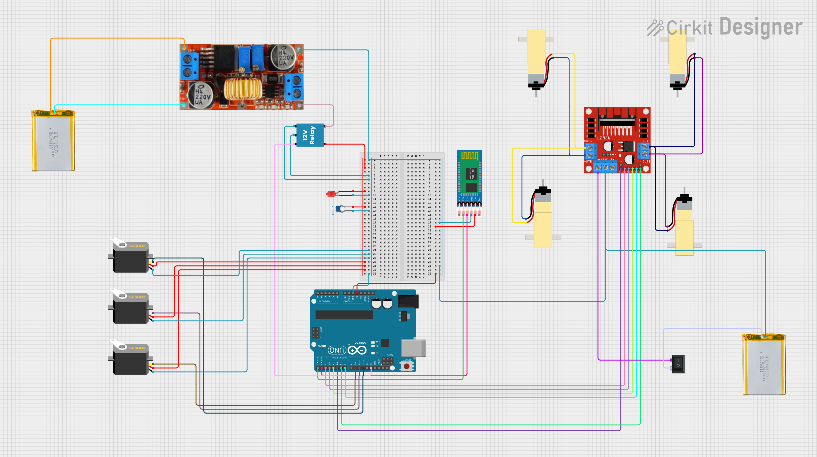
This circuit is designed to control multiple servos and hobby gearmotors through an Arduino UNO microcontroller. It includes a Bluetooth module (HC-05) for wireless communication, a motor driver (L298N) to drive the gearmotors, and a relay to switch higher power loads. Power management is handled by a step-down converter (XL4015) and a rocker switch. The circuit also features a red LED with a ceramic capacitor for noise suppression or indication purposes.
Component List
Microcontroller
- Arduino UNO: A microcontroller board based on the ATmega328P, featuring digital and analog I/O pins.
Actuators
- Servo: A rotary actuator or linear actuator that allows for precise control of angular or linear position.
- Hobby Gearmotor with 48:1 gearbox: A DC motor with a gearbox to reduce speed and increase torque.
Power Components
- XL4015 step down bulk converter: A DC-DC step-down (buck) converter module used to regulate voltage levels.
- 2000mAh Battery: A rechargeable battery providing the power source for the circuit.
- Rocker Switch (SPST): A single-pole single-throw switch used to connect or disconnect the circuit from power.
Communication Module
- HC-05: A commonly used Bluetooth module for serial communication.
Motor Driver
- L298N DC motor driver: A dual H-bridge motor driver used to control the direction and speed of two DC motors.
Relay
- 12V Relay: An electromechanical switch used to control a circuit by a separate low-power signal.
Indicators and Protection
- LED: Two Pin (red): A red light-emitting diode used as an indicator.
- Ceramic Capacitor: A capacitor used for filtering or noise suppression in the circuit.
Wiring Details
Arduino UNO
- Digital pins D0-D13 are used for controlling various components such as the HC-05 module, servos, motor driver, and relay.
- The 5V and GND pins provide power to the HC-05 module and ground connections to various components.
Servos
- Each servo has a ground (GND), power (VCC), and control (pulse) connection. The control lines are connected to different digital pins on the Arduino UNO for independent control.
Hobby Gearmotors
- The gearmotors are connected to the L298N motor driver's output pins. The driver controls the direction and speed of the motors.
XL4015 Step Down Bulk Converter
- The input is connected to a 2000mAh battery, and the output provides a regulated voltage to the relay and other components.
HC-05 Bluetooth Module
- The VCC and GND pins are connected to the 5V and GND on the Arduino UNO, respectively. The TXD and RXD pins are connected to the Arduino's RX and TX pins for serial communication.
L298N DC Motor Driver
- The input pins IN1-IN4 are connected to the Arduino's digital pins for motor control signals. The ENA and ENB pins are connected to PWM-capable pins on the Arduino for speed control. The 12V input is connected through the rocker switch, and the motor outputs are connected to the gearmotors.
12V Relay
- The coil pins (+ and -) are connected to the Arduino (for control) and ground. The common (C) and normally closed (NC) contacts are connected to the step-down converter's output and the red LED, respectively.
LED: Two Pin (red)
- The anode is connected to the normally closed contact of the relay, and the cathode is connected to the ground through a ceramic capacitor.
Rocker Switch (SPST)
- Used to connect or disconnect the 12V input to the L298N motor driver.
Documented Code
void setup() {
  // put your setup code here, to run once:

}

void loop() {
  // put your main code here, to run repeatedly:

}
The provided code is a template with empty setup() and loop() functions, which are the entry points for Arduino code. The setup() function is called once when the program starts and is used to initialize settings. The loop() function is called repeatedly and contains the main logic of the program. Actual implementation details need to be added to control the components as per the circuit design.