
Arduino UNO and NRF24L01 Controlled Motor System with Pushbutton and BTS7960 Driver
View and Edit Project In Cirkit Designer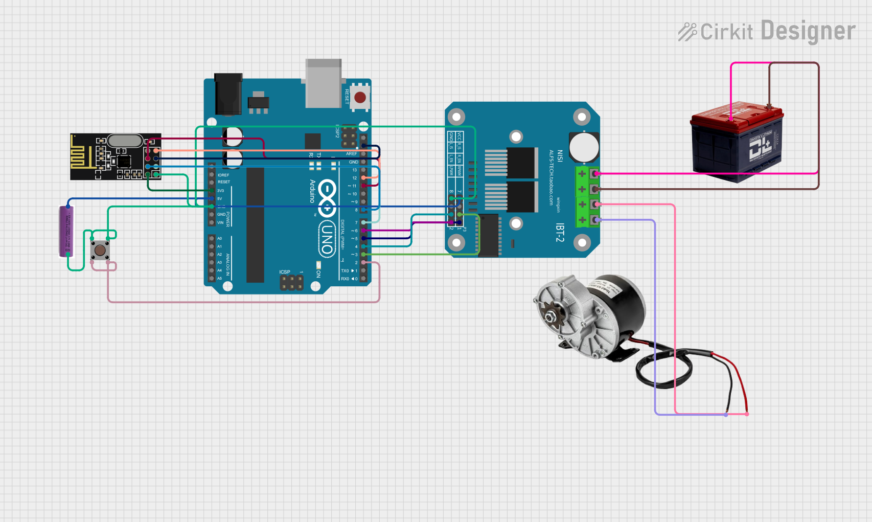
Circuit Documentation
Summary
This circuit is designed to control a 250W 12V DC motor using an Arduino UNO, a BTS7960 motor driver, and an NRF24L01 wireless module. The motor's speed and direction are controlled based on signals received from another NRF24L01 module. A pushbutton is used as an ON/OFF switch for the Arduino.
Component List
Arduino UNO
- Description: A microcontroller board based on the ATmega328P.
- Pins: UNUSED, IOREF, Reset, 3.3V, 5V, GND, Vin, A0, A1, A2, A3, A4, A5, SCL, SDA, AREF, D13, D12, D11, D10, D9, D8, D7, D6, D5, D4, D3, D2, D1, D0
BTS7960 Motor Driver
- Description: A high-power motor driver module.
- Pins: Pin 1, Pin 2, Pin 3, Pin 4, Pin 5, Pin 6, Pin 7, Pin 8, Pin 9, Pin 10, Pin 11, Pin 12
250W 12V ELECTRIC MOTOR BRUSH MOTOR DC
- Description: A 250W 12V DC motor.
- Pins: POSITIF, NEGATIF
Battery 12V
- Description: A 12V battery for powering the motor.
- Pins: -, +
NRF24L01
- Description: A wireless transceiver module.
- Pins: IRQ (not used), MOSI, CSN, VCC (3V), GND, CE, SCK, MISO
Pushbutton
- Description: A simple pushbutton switch.
- Pins: Pin 3 (out), Pin 4 (out), Pin 1 (in), Pin 2 (in)
3.7V Battery
- Description: A 3.7V battery for powering the Arduino and NRF24L01.
- Pins: +, -
Wiring Details
Arduino UNO
- 3.3V connected to NRF24L01 VCC (3V)
- 5V connected to BTS7960 Motor Driver Pin 5
- GND connected to 3.7V Battery -, BTS7960 Motor Driver Pin 1, NRF24L01 GND, Pushbutton Pin 3 (out)
- SDA connected to NRF24L01 SCK
- D12 connected to NRF24L01 MISO
- D11 connected to NRF24L01 MOSI
- D8 connected to NRF24L01 CSN
- D7 connected to NRF24L01 CE
- D6 connected to BTS7960 Motor Driver Pin 4
- D5 connected to BTS7960 Motor Driver Pin 8
- D4 connected to BTS7960 Motor Driver Pin 3
- D3 connected to BTS7960 Motor Driver Pin 7
- D2 connected to Pushbutton Pin 4 (out)
BTS7960 Motor Driver
- Pin 5 connected to Arduino UNO 5V
- Pin 1 connected to Arduino UNO GND
- Pin 4 connected to Arduino UNO D6
- Pin 8 connected to Arduino UNO D5
- Pin 3 connected to Arduino UNO D4
- Pin 7 connected to Arduino UNO D3
- Pin 9 connected to 250W 12V ELECTRIC MOTOR BRUSH MOTOR DC NEGATIF
- Pin 10 connected to 250W 12V ELECTRIC MOTOR BRUSH MOTOR DC POSITIF
- Pin 11 connected to Battery 12V +
- Pin 12 connected to Battery 12V -
250W 12V ELECTRIC MOTOR BRUSH MOTOR DC
- POSITIF connected to BTS7960 Motor Driver Pin 10
- NEGATIF connected to BTS7960 Motor Driver Pin 9
Battery 12V
- + connected to BTS7960 Motor Driver Pin 11
- - connected to BTS7960 Motor Driver Pin 12
NRF24L01
- VCC (3V) connected to Arduino UNO 3.3V
- GND connected to Arduino UNO GND
- SCK connected to Arduino UNO SDA
- MISO connected to Arduino UNO D12
- MOSI connected to Arduino UNO D11
- CSN connected to Arduino UNO D8
- CE connected to Arduino UNO D7
Pushbutton
- Pin 3 (out) connected to Arduino UNO GND
- Pin 4 (out) connected to Arduino UNO D2
- Pin 1 (in) connected to 3.7V Battery -
- Pin 2 (in) connected to Pushbutton Pin 4 (out)
3.7V Battery
- + connected to BTS7960 Motor Driver Pin 5
- - connected to Pushbutton Pin 1 (in)
Code Documentation
/*
 * This Arduino sketch receives signals from another nRF24L01 module and uses
 * those signals to control a motor via the BTS7960 motor driver. A pushbutton
 * is used as an ON/OFF switch for the Arduino.
 */

#include <SPI.h>
#include <nRF24L01.h>
#include <RF24.h>

// Pin definitions
#define CE_PIN 7
#define CSN_PIN 8
#define MOTOR_EN_PIN 5
#define MOTOR_PWM_PIN 6
#define MOTOR_DIR_PIN 4
#define MOTOR_BRAKE_PIN 3
#define BUTTON_PIN 2

// Create an RF24 object
RF24 radio(CE_PIN, CSN_PIN);

// Address for the nRF24L01 communication
const byte address[6] = "00001";

// Variable to store received data
int motorSpeed = 0;

void setup() {
  // Initialize serial communication
  Serial.begin(9600);

  // Initialize the nRF24L01 module
  radio.begin();
  radio.openReadingPipe(0, address);
  radio.setPALevel(RF24_PA_MIN);
  radio.startListening();

  // Initialize motor control pins
  pinMode(MOTOR_EN_PIN, OUTPUT);
  pinMode(MOTOR_PWM_PIN, OUTPUT);
  pinMode(MOTOR_DIR_PIN, OUTPUT);
  pinMode(MOTOR_BRAKE_PIN, OUTPUT);

  // Initialize button pin
  pinMode(BUTTON_PIN, INPUT_PULLUP);

  // Set initial motor state
  digitalWrite(MOTOR_EN_PIN, LOW);
  digitalWrite(MOTOR_BRAKE_PIN, HIGH);
}

void loop() {
  // Check if the button is pressed
  if (digitalRead(BUTTON_PIN) == LOW) {
    // If button is pressed, enable the motor
    digitalWrite(MOTOR_EN_PIN, HIGH);
    digitalWrite(MOTOR_BRAKE_PIN, LOW);
  } else {
    // If button is not pressed, disable the motor
    digitalWrite(MOTOR_EN_PIN, LOW);
    digitalWrite(MOTOR_BRAKE_PIN, HIGH);
  }

  // Check if data is available to read
  if (radio.available()) {
    // Read the data
    radio.read(&motorSpeed, sizeof(motorSpeed));

    // Set motor speed and direction
    if (motorSpeed >= 0) {
      digitalWrite(MOTOR_DIR_PIN, HIGH);
      analogWrite(MOTOR_PWM_PIN, motorSpeed);
    } else {
      digitalWrite(MOTOR_DIR_PIN, LOW);
      analogWrite(MOTOR_PWM_PIN, -motorSpeed);
    }
  }
}
This code initializes the NRF24L01 module for wireless communication, sets up the motor control pins, and reads the state of the pushbutton to control the motor. The motor speed and direction are adjusted based on the received signals from another NRF24L01 module.