
Circuit Documentation
Summary of the Circuit
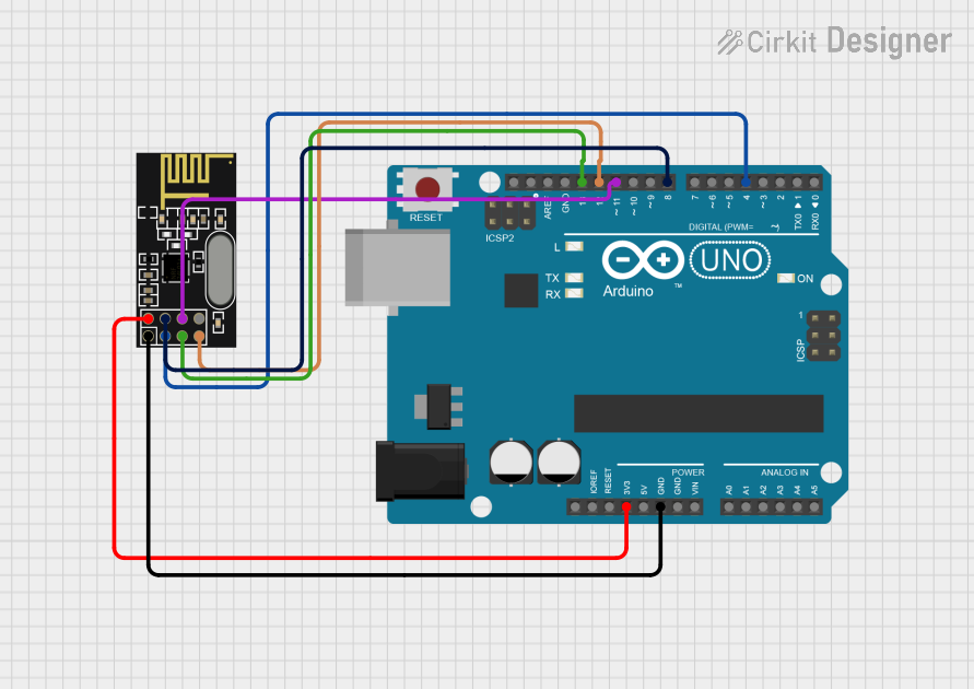
This circuit integrates an Arduino UNO microcontroller board with an NRF24L01 wireless transceiver module. The purpose of the circuit is to establish a wireless communication link, allowing the Arduino UNO to send data wirelessly through the NRF24L01 module. The Arduino UNO is programmed to transmit a "Hello World" message at regular intervals using the RF24 library, which facilitates communication with the NRF24L01 module.
Component List
Arduino UNO
- Description: A microcontroller board based on the ATmega328P.
- Purpose: Acts as the central processing unit of the circuit, controlling the NRF24L01 module and executing the embedded code for wireless communication.
- Pins: UNUSED, IOREF, Reset, 3.3V, 5V, GND, Vin, A0-A5, SCL, SDA, AREF, D0-D13.
NRF24L01
- Description: A 2.4GHz wireless transceiver module.
- Purpose: Enables wireless communication with compatible devices.
- Pins: IRQ (not used), MOSI, CSN, VCC (3V), GND, CE, SCK, MISO.
Wiring Details
Arduino UNO
- 3.3V connected to NRF24L01 VCC (3V)
- GND connected to NRF24L01 GND
- D13 (SCK) connected to NRF24L01 SCK
- D12 (MISO) connected to NRF24L01 MISO
- D11 (MOSI) connected to NRF24L01 MOSI
- D8 (CSN) connected to NRF24L01 CSN
- D4 (CE) connected to NRF24L01 CE
NRF24L01
- VCC (3V) connected to Arduino UNO 3.3V
- GND connected to Arduino UNO GND
- SCK connected to Arduino UNO D13 (SCK)
- MISO connected to Arduino UNO D12 (MISO)
- MOSI connected to Arduino UNO D11 (MOSI)
- CSN connected to Arduino UNO D8 (CSN)
- CE connected to Arduino UNO D4 (CE)
Documented Code
Arduino UNO Code (Tx.ino)
#include <SPI.h>
#include <nRF24L01.h>
#include <RF24.h>

RF24 radio(7, 8); // Initialize nRF24L01 radio on SPI bus with CE, CSN pins declared.

const byte address[6] = "00001"; // Address for transmitter and receiver communication.

void setup() {
  radio.begin();
  radio.openWritingPipe(address); // Set the address of the receiver to send data to.
  radio.setPALevel(RF24_PA_MIN); // Set the power level of the module. Use RF24_PA_MIN for close proximity.

  // Power levels can be set to RF24_PA_MIN, RF24_PA_LOW, RF24_PA_HIGH, RF24_PA_MAX.
  // For higher levels (longer distances), it is recommended to use a bypass capacitor on GND and 3.3V to ensure stable voltage during operation.

  radio.stopListening(); // Set the module as a transmitter.
}

void loop() {
  const char text[] = "Hello World";
  radio.write(&text, sizeof(text)); // Send the message to the receiver.
  delay(1000);
}
NRF24L01 Code (sketch.ino)
void setup() {
  // Setup code to run once:
}

void loop() {
  // Main code to run repeatedly:
}
This code for the NRF24L01 is a placeholder, as the actual logic for receiving or further processing of data would be implemented depending on the specific application requirements.