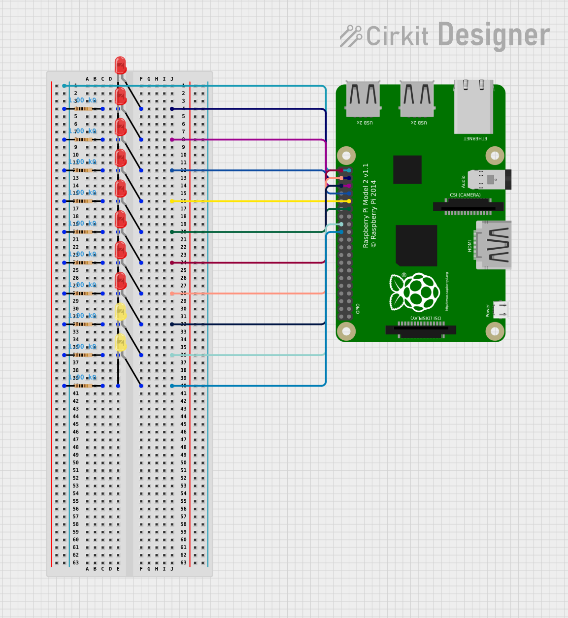
Raspberry Pi-Controlled Multi-LED Indicator System

Circuit Documentation
Summary
The circuit in question appears to be a simple LED array controlled by a Raspberry Pi 2B. The array consists of multiple LEDs, both red and yellow, each paired with a resistor to limit the current. The Raspberry Pi's GPIO pins are used to control the state of the LEDs, allowing them to be turned on or off individually. The ground connections for all the resistors are tied together and connected to the Raspberry Pi's ground pin.
Component List
LEDs
- LED: Two Pin (red): A standard red LED with two pins, anode and cathode.
- LED: Two Pin (yellow): A standard yellow LED with two pins, anode and cathode.
Resistors
- Resistor: A standard resistor with a resistance of 1000 Ohms (1 kΩ).
Microcontroller
- Raspberry Pi 2B: A microcontroller board with multiple GPIO pins used for controlling the LEDs.
Wiring Details
Raspberry Pi 2B
- GPIO Pins: Used to control the state of the LEDs.
- GND: Connected to the cathode side of the resistors to complete the circuit for each LED.
LEDs (Red and Yellow)
- Anode: Connected to a GPIO pin on the Raspberry Pi 2B.
- Cathode: Connected to a resistor, which is then connected to the Raspberry Pi's GND.
Resistors
- Pin1: Connected to the Raspberry Pi's GND.
- Pin2: Connected to the cathode of an LED.
Documented Code
There is no code provided for the microcontroller in this circuit. The expected code would typically initialize the GPIO pins on the Raspberry Pi 2B and set them to output mode. Then, it would control the state of each pin to turn the corresponding LED on or off.
Please note that without the actual code, we cannot provide a detailed documentation of the software part of this circuit. The code would be necessary to understand the logic behind the LED control and any specific behaviors implemented in the circuit.