Arduino UNO Reed Switch Sensor with LED Indicator
Circuit Documentation
Summary of the Circuit
This circuit is designed to monitor the state of a reed switch and control an onboard LED on an Arduino UNO microcontroller based on the reed switch's state. When the reed switch is closed (e.g., a magnet is near), the onboard LED will turn on, and a message "Switch closed" will be printed to the serial monitor. Conversely, when the reed switch is open, the LED will turn off, and a message "Switch opened" will be printed.
Component List
Reed Switch
- Description: A magnetic field-activated switch.
- Pins:
- pin 1
- pin 2
Arduino UNO
- Description: A microcontroller board based on the ATmega328P.
- Pins: UNUSED, IOREF, Reset, 3.3V, 5V, GND, Vin, A0 to A5, SCL, SDA, AREF, D0 to D13
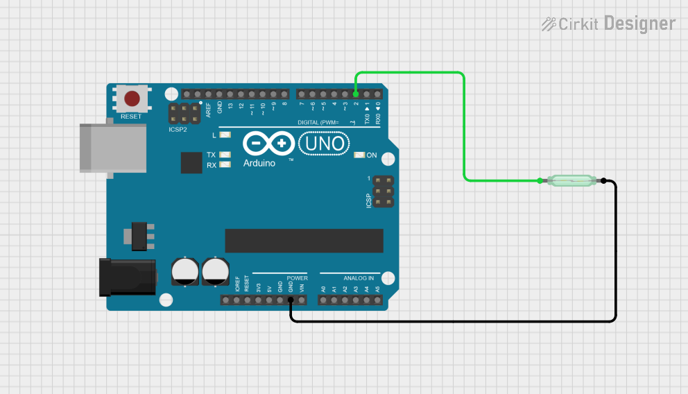
Wiring Details
Reed Switch
- pin 1: Connected to Arduino UNO pin D2.
- pin 2: Connected to Arduino UNO pin GND.
Arduino UNO
- D2: Connected to Reed Switch pin 1.
- GND: Connected to Reed Switch pin 2.
- D13: Used to control the onboard LED.
- Other Pins: Not used in this circuit.
Documented Code
Arduino UNO Code: sketch.ino
/* Reed Switch and LED Control
 * This sketch is designed to monitor the state of a reed switch connected to pin D2 of the Arduino UNO.
 * When the reed switch is closed (e.g., a magnet is near), the onboard LED connected to pin D13 will turn on,
 * and a message "Switch closed" will be printed to the serial monitor.
 * When the reed switch is open, the LED will turn off, and a message "Switch opened" will be printed.
 * The reed switch is connected with an internal pull-up resistor.
 */

const int REED_PIN = 2;  // Pin connected to reed switch
const int LED_PIN = 13;  // LED pin (onboard LED on Arduino UNO)

void setup() {
  Serial.begin(9600);                // Start serial communication at 9600 baud
  pinMode(REED_PIN, INPUT_PULLUP);   // Enable internal pull-up for the reed switch
  pinMode(LED_PIN, OUTPUT);          // Set the LED pin as an output
}

void loop() {
  int proximity = digitalRead(REED_PIN); // Read the state of the switch

  // If the pin reads low, the switch is closed.
  if (proximity == LOW) {
    Serial.println("Switch closed");    // Print message to the serial monitor
    digitalWrite(LED_PIN, HIGH);        // Turn the LED on
  }
  else {
    Serial.println("Switch opened");    // Print message to the serial monitor
    digitalWrite(LED_PIN, LOW);         // Turn the LED off
  }
}
This code is responsible for the operation of the circuit as described in the summary. It initializes the serial communication, configures the reed switch pin with an internal pull-up resistor, and sets the LED pin as an output. In the main loop, it reads the state of the reed switch and turns the onboard LED on or off accordingly, while also printing the state to the serial monitor.