ESP32-Controlled Load Cell and Ultrasonic Sensor System with Status LEDs
Circuit Documentation
Summary of the Circuit
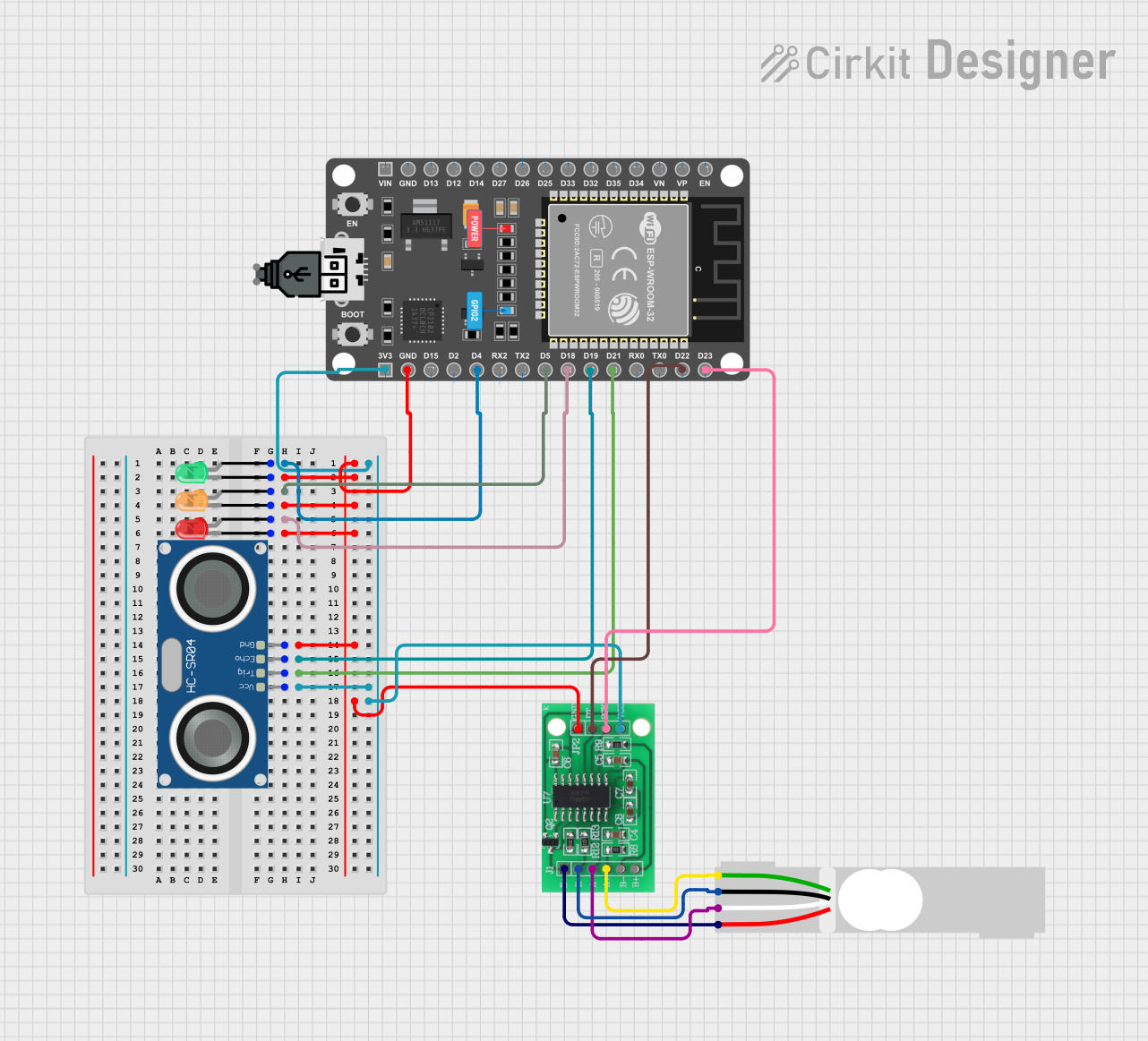
The circuit described by the provided inputs consists of several components including a load cell interfaced with an HX711 bridge sensor interface, an HC-SR04 ultrasonic sensor, three LEDs of different colors (green, orange, and red), and an ESP32 DEVKIT V1 microcontroller. The circuit is designed to measure weight using the load cell, detect distance with the ultrasonic sensor, and provide visual indicators through the LEDs. The ESP32 microcontroller serves as the central processing unit, controlling the sensors and LEDs. The HX711 module amplifies the signals from the load cell, and the ESP32 reads these signals as well as the distance measurements from the HC-SR04 sensor. The LEDs are used as status indicators. The circuit is powered by a USB power source.
Component List
Load Cell - Red/white/black/green
A sensor used for measuring weight or force.
HX711 - Bridge Sensor Interface
A precision 24-bit analog-to-digital converter (ADC) designed for weigh scales and industrial control applications to interface directly with a bridge sensor.
HC-SR04 Ultrasonic Sensor
An ultrasonic distance sensor that provides 2cm to 400cm of non-contact measurement functionality with a ranging accuracy that can reach up to 3mm.
LED: Two Pin (green)
A green light-emitting diode used as an indicator.
LED: Two Pin (red)
A red light-emitting diode used as an indicator.
LED: Two Pin (orange)
An orange light-emitting diode used as an indicator.
ESP 32 DEVKIT V1 (30 pins)
A microcontroller with Wi-Fi and Bluetooth capabilities, suitable for a variety of IoT applications.
USB power
A power source that provides power to the circuit through a USB connection.
Wiring Details
Load Cell - Red/white/black/green
- E+: Connected to HX711 E+
- A-: Connected to HX711 A-
- E-: Connected to HX711 E-
- A+: Connected to HX711 A+
HX711 - Bridge Sensor Interface
- E+: Connected to Load Cell E+
- E-: Connected to Load Cell E-
- A-: Connected to Load Cell A-
- A+: Connected to Load Cell A+
- B-: Not connected
- B+: Not connected
- GND - GROUND: Connected to common ground
- DATA (OUT): Connected to ESP32 D22
- SCK - CLOCK (IN): Connected to ESP32 D23
- 3.3/3.5V Supply: Connected to ESP32 3V3
HC-SR04 Ultrasonic Sensor
- VCC: Connected to ESP32 3V3
- TRIG: Connected to ESP32 D21
- ECHO: Connected to ESP32 D19
- GND: Connected to common ground
LED: Two Pin (green)
- Anode: Connected to ESP32 D4
- Cathode: Connected to common ground
LED: Two Pin (red)
- Anode: Connected to ESP32 D18
- Cathode: Connected to common ground
LED: Two Pin (orange)
- Anode: Connected to ESP32 D5
- Cathode: Connected to common ground
ESP 32 DEVKIT V1 (30 pins)
- D4: Connected to green LED anode
- D5: Connected to orange LED anode
- D18: Connected to red LED anode
- D19: Connected to HC-SR04 ECHO
- D21: Connected to HC-SR04 TRIG
- D22: Connected to HX711 DATA (OUT)
- D23: Connected to HX711 SCK - CLOCK (IN)
- 3V3: Connected to HC-SR04 VCC and HX711 3.3/3.5V Supply
- GND: Connected to common ground
USB power
- +: Not directly connected to any component in the circuit
- -: Not directly connected to any component in the circuit
Documented Code
No code has been provided for the microcontroller. The documentation of the code would typically include setup routines, main loop logic, functions for sensor data acquisition, processing, and output control for the LEDs. Since no code is available, this section cannot be completed.