Cirkit Designer
Your all-in-one circuit design IDE
Home /
Project Documentation
Arduino-Based RFID Access Control System with LCD Display
Circuit Documentation
Summary
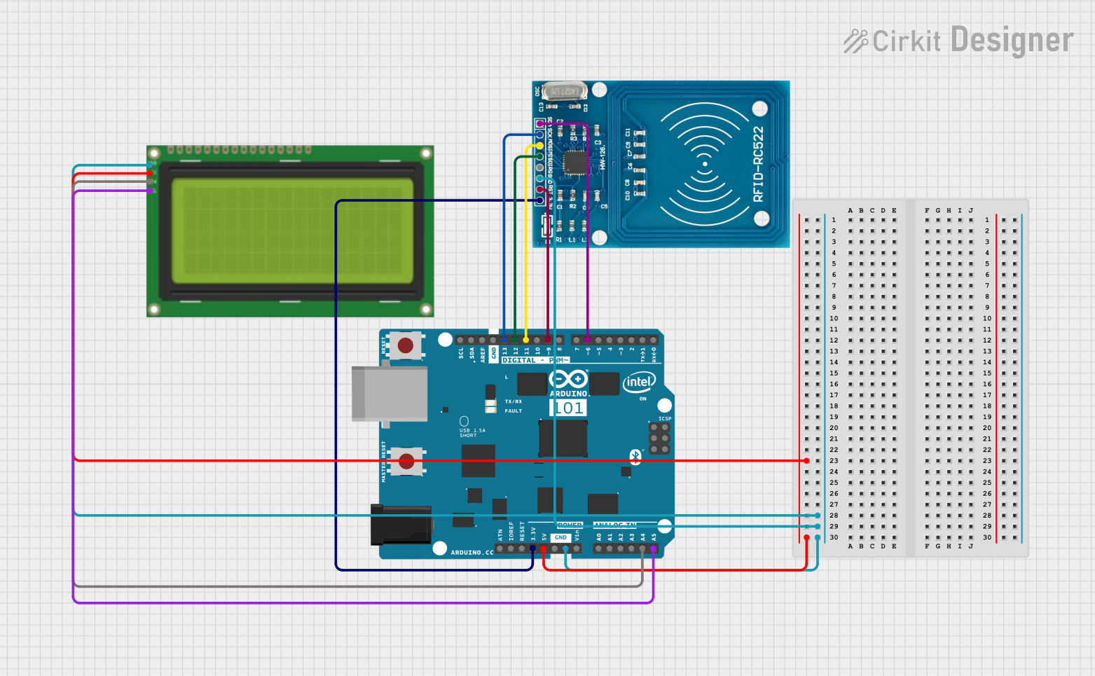
This document provides a detailed overview of a circuit that integrates an RFID reader, an Arduino 101 microcontroller, and an LCD display. The RFID reader is used for reading RFID tags, the Arduino 101 serves as the central processing unit, and the LCD display is used for visual output. The document includes a list of components, wiring details, and code documentation.
Component List
RFID-RC522
- Description: RFID reader module
- Pins: VCC (3.3V), RST, GND, IRQ, MISO, MOSI, SCK, SDA
- Purpose: Used for reading RFID tags
Arduino 101
- Description: Microcontroller board
- Pins: A5/SCL, A4/SDA, AREF, GND, D13/SCK, D12/MISO, D11 PWM/MOSI, D10 PWM/SS, D9 PWM, D8, D7, D6 PWM, D5 PWM, D4, D3 PWM, D2, D1/TX, D0/RX, AIN, ioref, RESET, 3V3, 5V, VIN, A0, A1, A2, A3, ICSP MISO, ICSP SCK, ICSP MOSI
- Purpose: Central processing unit
Lcd 20x4 i2c
- Description: 20x4 character LCD display with I2C interface
- Pins: GND, 5v, SCA, SCL
- Purpose: Display output
Wiring Details
RFID-RC522
- VCC (3.3V): Connected to Arduino 101 pin 3V3
- RST: Connected to Arduino 101 pin D9 PWM
- GND: Connected to Arduino 101 pin GND and Lcd 20x4 i2c pin GND
- MISO: Connected to Arduino 101 pin D12/MISO
- MOSI: Connected to Arduino 101 pin D11 PWM/MOSI
- SCK: Connected to Arduino 101 pin D13/SCK
- SDA: Connected to Arduino 101 pin D6 PWM
Arduino 101
- 3V3: Connected to RFID-RC522 pin VCC (3.3V)
- D9 PWM: Connected to RFID-RC522 pin RST
- GND: Connected to RFID-RC522 pin GND and Lcd 20x4 i2c pin GND
- D12/MISO: Connected to RFID-RC522 pin MISO
- D11 PWM/MOSI: Connected to RFID-RC522 pin MOSI
- D13/SCK: Connected to RFID-RC522 pin SCK
- D6 PWM: Connected to RFID-RC522 pin SDA
- A5/SCL: Connected to Lcd 20x4 i2c pin SCL
- 5V: Connected to Lcd 20x4 i2c pin 5v
- A4/SDA: Connected to Lcd 20x4 i2c pin SCA
Lcd 20x4 i2c
- GND: Connected to Arduino 101 pin GND and RFID-RC522 pin GND
- 5v: Connected to Arduino 101 pin 5V
- SCA: Connected to Arduino 101 pin A4/SDA
- SCL: Connected to Arduino 101 pin A5/SCL
Code Documentation
No code is provided for this circuit. If code is added in the future, it should be documented here with detailed explanations of its functionality and how it interacts with the hardware components.