Cirkit Designer
Your all-in-one circuit design IDE
Home /
Project Documentation
ESP32-Based Smart Arena System with IR Sensor, Keypad, and OLED Display
Circuit Documentation
Summary
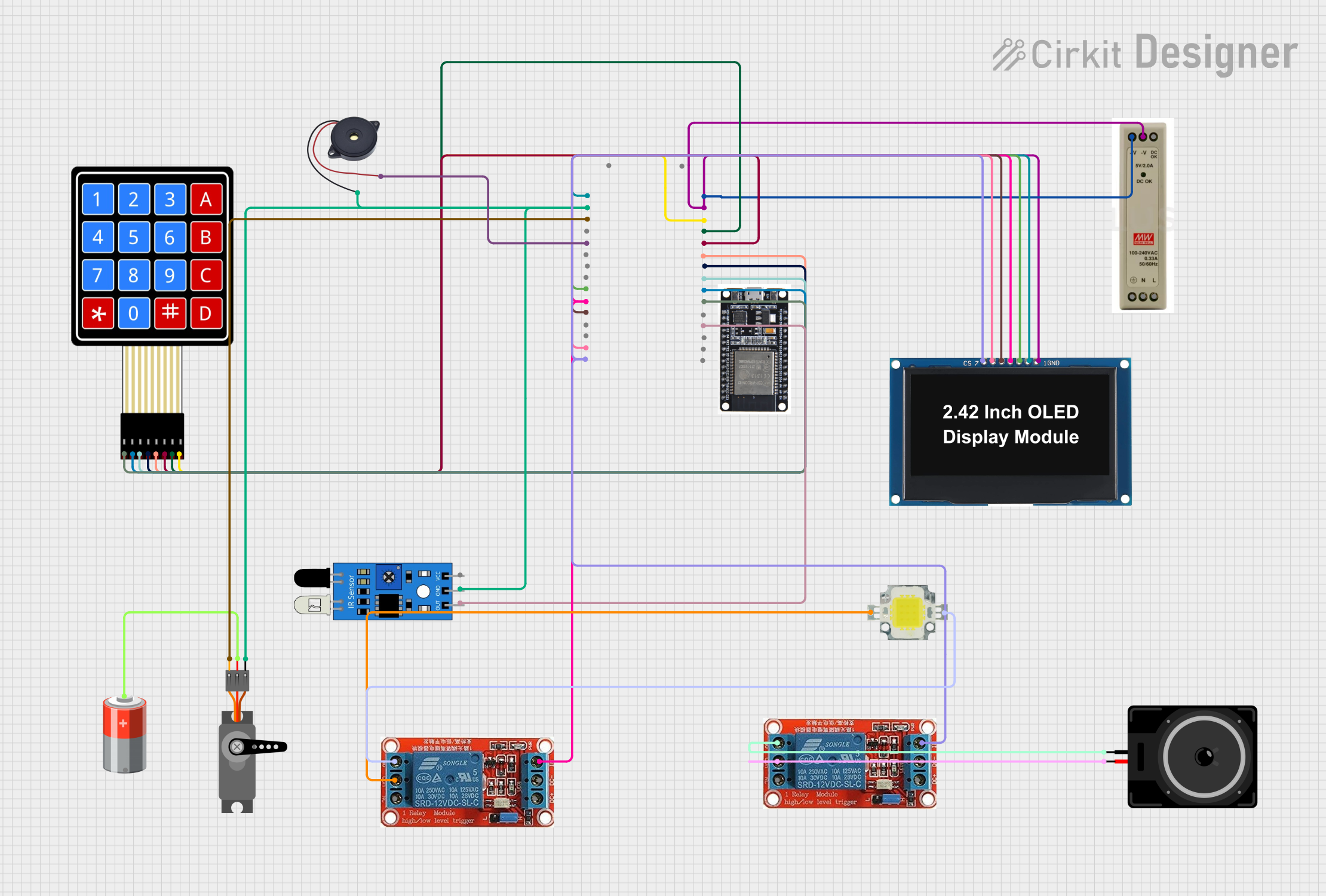
This document provides a detailed overview of a circuit design that includes an ESP32 microcontroller, an IR sensor, a 4x4 membrane matrix keypad, a servo motor, an OLED display, two 12V relays, a loudspeaker, a 5V power supply unit (PSU), a 5V battery, a 12V power LED, and a buzzer. The circuit is designed to detect objects using the IR sensor, control relays and a servo motor, display information on an OLED screen, and provide audio feedback through a buzzer and loudspeaker.
Component List
ESP32
- Description: Microcontroller with Wi-Fi and Bluetooth capabilities.
- Pins: EN, VP, VN, D34, D35, D32, D33, D25, D26, D27, D14, D12, D13, GND, VIN, 3V3, D15, D2, D4, RX2, TX2, D5, D18, D19, D21, RX0, TX0, D22, D23, BOOT
IR Sensor
- Description: Infrared sensor for object detection.
- Pins: out, gnd, vcc
4x4 Membrane Matrix Keypad
- Description: Keypad with 4 rows and 4 columns.
- Pins: R1, R2, R3, R4, C1, C2, C3, C4
Servo
- Description: Servo motor for precise control of angular position.
- Pins: GND, VCC, PWM
OLED Display 2.42"
- Description: 2.42-inch OLED display.
- Pins: GND, VCC, SCK, SDA, RES, DC, CS
12V Relay
- Description: Relay for switching high voltage devices.
- Pins: NO, COM, NC, IN, DC-, DC+
Loudspeaker
- Description: Loudspeaker for audio output.
- Pins: pin1, pin2
5V PSU
- Description: 5V power supply unit.
- Pins: 5V+, GND, 5V OK, PE, N, L
5V Battery
- Description: 5V battery for power supply.
- Pins: +, -
Power LED 12V 10W 0.8-0.9A
- Description: High-power LED.
- Pins: +, -
Buzzer
- Description: Buzzer for audio feedback.
- Pins: GND, IN
Wiring Details
ESP32
- D34 connected to IR Sensor out
- D32 connected to Keypad R1
- D33 connected to Keypad R2
- D25 connected to Keypad R3
- D26 connected to Keypad R4
- D27 connected to Keypad C1
- D14 connected to Keypad C2
- D12 connected to Keypad C3
- D13 connected to Keypad C4
- GND connected to 5V PSU GND, OLED Display GND, IR Sensor gnd, Buzzer GND, Servo GND
- VIN connected to 5V PSU 5V+
- 3V3 connected to OLED Display VCC
- D15 connected to Servo PWM
- D4 connected to Buzzer IN
- D18 connected to OLED Display SCK
- D19 connected to OLED Display SDA, Relay 1 IN
- D21 connected to OLED Display RES
- D22 connected to OLED Display DC
- D23 connected to OLED Display CS, Relay 2 IN
IR Sensor
- out connected to ESP32 D34
- gnd connected to ESP32 GND
- vcc connected to 5V PSU 5V+
4x4 Membrane Matrix Keypad
- R1 connected to ESP32 D32
- R2 connected to ESP32 D33
- R3 connected to ESP32 D25
- R4 connected to ESP32 D26
- C1 connected to ESP32 D27
- C2 connected to ESP32 D14
- C3 connected to ESP32 D12
- C4 connected to ESP32 D13
Servo
- GND connected to ESP32 GND
- VCC connected to 5V Battery +
- PWM connected to ESP32 D15
OLED Display 2.42"
- GND connected to ESP32 GND
- VCC connected to ESP32 3V3
- SCK connected to ESP32 D18
- SDA connected to ESP32 D19
- RES connected to ESP32 D21
- DC connected to ESP32 D22
- CS connected to ESP32 D23
12V Relay 1
- NO connected to Power LED -
- COM connected to Power LED +
- IN connected to ESP32 D19
- DC- connected to 5V PSU GND
- DC+ connected to 5V PSU 5V+
12V Relay 2
- NO connected to Loudspeaker pin1
- COM connected to Loudspeaker pin2
- IN connected to ESP32 D23
- DC- connected to 5V PSU GND
- DC+ connected to 5V PSU 5V+
Loudspeaker
- pin1 connected to Relay 2 NO
- pin2 connected to Relay 2 COM
5V PSU
- 5V+ connected to ESP32 VIN, OLED Display VCC, IR Sensor vcc, Relay 1 DC+, Relay 2 DC+
- GND connected to ESP32 GND, OLED Display GND, IR Sensor gnd, Buzzer GND, Servo GND, Relay 1 DC-, Relay 2 DC-
5V Battery
- + connected to Servo VCC
- - not connected
Power LED 12V 10W 0.8-0.9A
- + connected to Relay 1 COM
- - connected to Relay 1 NO
Buzzer
- GND connected to ESP32 GND
- IN connected to ESP32 D4
Documented Code
#include <Wire.h>
#include <Adafruit_GFX.h>
#include <Adafruit_SSD1306.h>
#include <Keypad.h>
#include <ESP32Servo.h> // Use the correct Servo library for ESP32

// OLED display settings
#define SCREEN_WIDTH 128
#define SCREEN_HEIGHT 64
#define OLED_RESET    -1
#define SSD1306_I2C_ADDRESS 0x3C // Define the I2C address for the OLED
Adafruit_SSD1306 display(SCREEN_WIDTH, SCREEN_HEIGHT, &Wire, OLED_RESET);

// Keypad settings
const byte ROWS = 4; // Four rows
const byte COLS = 4; // Four columns
char keys[ROWS][COLS] = {
  {'1','2','3','A'},
  {'4','5','6','B'},
  {'7','8','9','C'},
  {'*','0','#','D'}
};
byte rowPins[ROWS] = {32, 33, 25, 26}; // Connect to the row pinouts of the keypad
byte colPins[COLS] = {27, 14, 12, 13}; // Connect to the column pinouts of the keypad
Keypad keypad = Keypad(makeKeymap(keys), rowPins, colPins, ROWS, COLS);

// Servo settings
Servo myservo;
const int servoPin = 15;

// IR sensor settings
const int irSensorPin = 34;

// Relay settings
const int relay1Pin = 19;
const int relay2Pin = 23;

// Buzzer settings
const int buzzerPin = 4;

void setup() {
  // Initialize serial communication
  Serial.begin(115200);

  // Initialize OLED display
  if(!display.begin