
ESP8266 NodeMCU Wi-Fi Controlled Temperature and Humidity Fan System
View and Edit Project In Cirkit Designer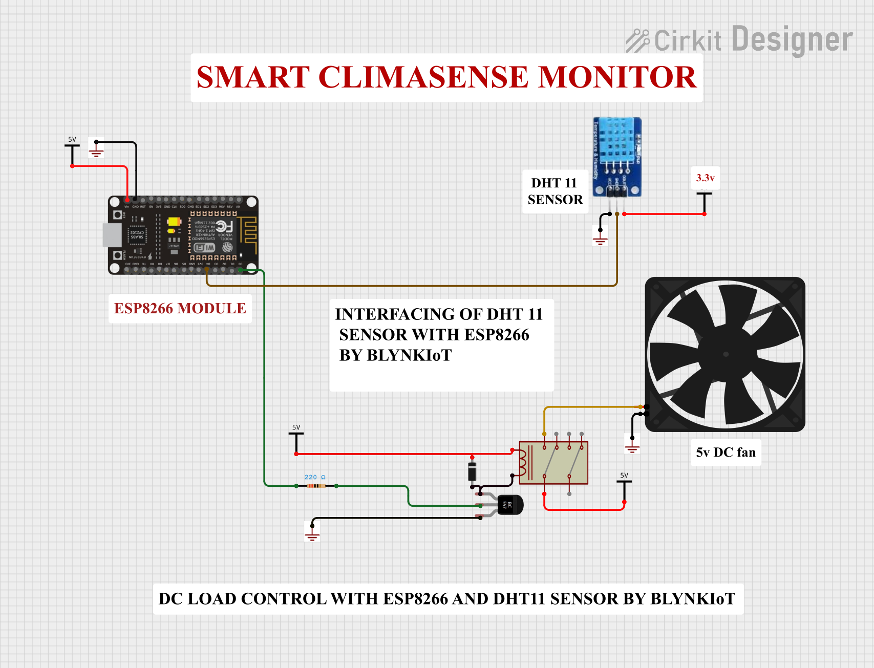
Circuit Documentation
Summary
This document provides a detailed overview of an electrical circuit designed to interface an ESP8266 NodeMCU microcontroller with various components including a DHT11 temperature and humidity sensor, a relay module, a transistor, a diode, a resistor, and a fan. The circuit is powered by a Vcc source and includes ground connections. The ESP8266 NodeMCU is programmed to interact with the connected components, potentially for home automation or environmental monitoring purposes.
Component List
Power Sources
- Vcc: A power supply input for the circuit.
- GND: Ground connections for the circuit.
Active Components
- ESP8266 NodeMCU: A microcontroller with WiFi capabilities, equipped with multiple GPIO pins and power connections.
- BC547 Transistor: An NPN transistor used for switching or amplification.
- Relay: An electromechanical switch that allows controlling high power devices with low power signals.
- Fan: A 5V fan used for cooling or ventilation.
Passive Components
- Resistor (220 Ohms): A resistor with a resistance of 220 Ohms, used for current limiting or voltage division.
- Diode: A semiconductor device that allows current to flow in one direction only, used for protection or rectification.
Sensors
- DHT11: A digital temperature and humidity sensor with a data output.
Comments
- Comment: Textual annotations or notes that are not part of the physical circuit but may provide additional information or instructions.
Wiring Details
ESP8266 NodeMCU
- D0: Connected to one end of the Resistor.
- D4: Connected to the GND pin of the DHT11 sensor.
- GND: Connected to the GND power source.
- VIN: Connected to the Vcc power source.
Resistor (220 Ohms)
- One end connected to the D0 pin of the ESP8266 NodeMCU.
- The other end connected to the Base pin of the BC547 Transistor.
BC547 Transistor
- Emitter: Connected to the GND power source.
- Base: Connected to the other end of the Resistor (220 Ohms).
- Collector: Connected to the Coil pin of the Relay and the anode of the Diode.
Relay
- Common 1: Connected to the Vcc power source.
- Coil: Connected to the Vcc power source and the Collector pin of the BC547 Transistor.
- NO 1: Connected to the 5V pin of the Fan.
Diode
- Cathode: Connected to the Vcc power source.
- Anode: Connected to the Coil pin of the Relay and the Collector pin of the BC547 Transistor.
Fan
- 5V: Connected to the NO 1 pin of the Relay.
- GND: Connected to the GND power source.
DHT11
- DATA: Connected to the Vcc power source.
- GND: Connected to the D4 pin of the ESP8266 NodeMCU.
- VCC: Connected to the GND power source.
Documented Code
ESP8266 NodeMCU (sketch.ino)
void setup() {
  // put your setup code here, to run once:

}

void loop() {
  // put your main code here, to run repeatedly:

}
ESP8266 NodeMCU (documentation.txt)
(No additional documentation provided for the code)
This concludes the documentation for the given circuit. The circuit is designed to control a fan using a relay, which is driven by a transistor switched by the ESP8266 NodeMCU. The DHT11 sensor provides environmental data, and the diode ensures protection against back EMF from the relay coil. The ESP8266 NodeMCU's code is currently a template and should be further developed to implement the desired functionality.