
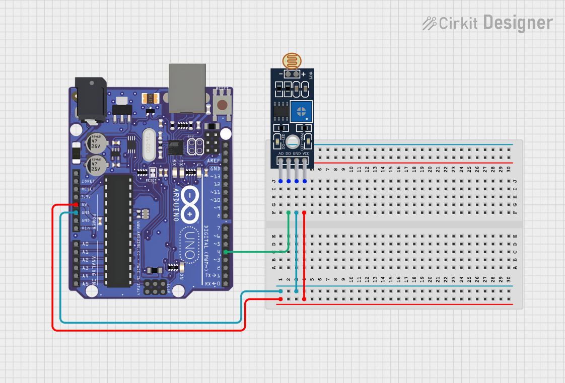
Circuit Documentation
Summary of the Circuit
This circuit consists of an Arduino UNO microcontroller board interfaced with a Sensor LDR LM393 module. The purpose of this circuit is not explicitly defined in the provided information, but typically, an LDR (Light Dependent Resistor) sensor is used to measure the intensity of light. The Arduino UNO can process this information and perform actions based on light intensity, such as turning on a light when it gets dark.
Component List
Arduino UNO
- Description: A microcontroller board based on the ATmega328P. It has 14 digital input/output pins, 6 analog inputs, a 16 MHz quartz crystal, a USB connection, a power jack, an ICSP header, and a reset button.
- Purpose in Circuit: Acts as the central processing unit for the circuit, reading sensor data and executing embedded code to perform tasks based on sensor input.
Sensor LDR LM393
- Description: A light sensor module that includes an LDR and an LM393 comparator for producing a digital signal that indicates light intensity.
- Purpose in Circuit: Measures the ambient light level and provides a digital output that can be read by the Arduino UNO.
Wiring Details
Arduino UNO
- Digital Pin D4: Connected to the digital output (D0) of the Sensor LDR LM393.
- Ground (GND): Shared with the Sensor LDR LM393 to provide a common reference point for the voltages in the circuit.
- 5V Pin: Supplies power to the Sensor LDR LM393 module.
Sensor LDR LM393
- Digital Output (D0): Connected to digital pin D4 of the Arduino UNO to send the digital signal representing light intensity.
- Ground (GND): Connected to the ground (GND) of the Arduino UNO to complete the circuit.
- VCC: Connected to the 5V output of the Arduino UNO to power the sensor.
Documented Code
No code has been provided for the microcontroller. To fully utilize this circuit, embedded code for the Arduino UNO is required. The code would typically initialize the digital pin connected to the sensor as an input, read the sensor's digital output, and then perform actions based on the sensor reading, such as turning on or off an LED or sending the data to a computer for logging.
Please note that without the specific purpose of the circuit and the embedded code, the documentation is limited to the physical connections and the general function of the components. For a complete documentation, the intended use case and the corresponding code should be provided.