
Voice-Controlled P10 LED Matrix Display with Arduino and Bluetooth
View and Edit Project In Cirkit Designer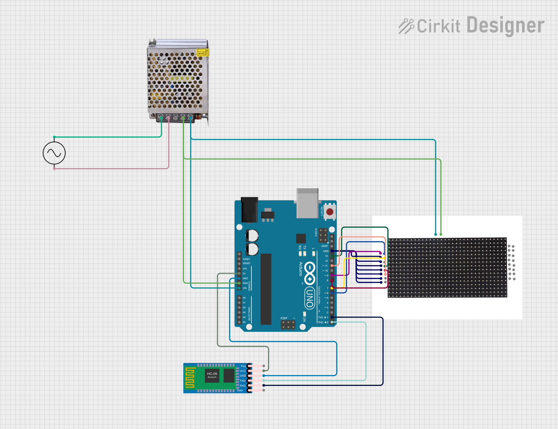
Circuit Documentation
Summary
This circuit is designed to control a 16x32 P10 LED matrix display using an Arduino UNO microcontroller and receive commands via a HC-05 Bluetooth module. The display is intended to show messages that are sent through the Bluetooth connection. The Arduino UNO is powered by a 5V 5A power supply, which also powers the LED matrix display. The HC-05 Bluetooth module is interfaced with the Arduino for wireless communication. The power supply is connected to an AC source to provide the necessary power for the circuit.
Component List
Arduino UNO
- Microcontroller board based on the ATmega328P
- It has 14 digital input/output pins, 6 analog inputs, a 16 MHz quartz crystal, a USB connection, a power jack, an ICSP header, and a reset button.
16x32 P10 LED Matrix Display
- A 16x32 pixel LED matrix display that is used for displaying messages and graphics.
- It requires a 5V power supply and digital control signals for operation.
HC-05 Bluetooth Module
- A wireless Bluetooth transceiver module that allows for serial communication.
- It is used to receive voice commands or messages from a Bluetooth-enabled device.
AC Supply
- Provides the alternating current (AC) power source for the circuit.
POWER SUPPLY 5V 5AMP
- A power supply unit that converts AC to a 5V 5A DC output.
- It powers the Arduino UNO and the LED matrix display.
Wiring Details
Arduino UNO
5VandGNDare connected to the HC-05 Bluetooth Module for power.Vinis connected to the 12V-24V Output (DC) from the POWER SUPPLY 5V 5AMP.GNDis also connected to the GND (DC) of the POWER SUPPLY 5V 5AMP and the-VEof the LED matrix display.- Digital pins
D13,D11,D9,D8,D7,D6,D1,D0are used for controlling the LED matrix display and communicating with the HC-05 Bluetooth Module.
16x32 P10 LED Matrix Display
+VE 5Vis connected to the 12V-24V Output (DC) from the POWER SUPPLY 5V 5AMP.- Multiple
GNDpins are connected to the GND of the Arduino UNO. DATA,CLK,enable,SCLK,B,Apins are controlled by the corresponding digital pins on the Arduino UNO.
HC-05 Bluetooth Module
VCCis connected to the5Von the Arduino UNO.GNDis connected to theGNDon the Arduino UNO.TXDandRXDare connected to theD0(RX) andD1(TX) on the Arduino UNO for serial communication.
AC Supply
+veand-veare connected to the corresponding 220V Positive Pole (AC) and 220V Negative Pole (AC) of the POWER SUPPLY 5V 5AMP.
POWER SUPPLY 5V 5AMP
220V Positive Pole (AC)and220V Negative Pole (AC)are connected to the AC Supply.GND (DC)and12V-24V Output (DC)provide the necessary DC power to the Arduino UNO and the LED matrix display.
Documented Code
/*
 * Arduino Sketch for Voice Controlled Red Color P10 LED Matrix Display
 * using Arduino UNO and HC-05 Bluetooth Module
 *
 * This code receives voice commands via Bluetooth from an HC-05 module
 * and displays the corresponding messages on a 16x32 P10 LED matrix display.
 */

#include <Adafruit_GFX.h>
#include <RGBmatrixPanel.h>

#define CLK 13  // P10 LED Matrix CLK pin
#define OE 9    // P10 LED Matrix OE pin
#define LAT 8   // P10 LED Matrix LAT pin
#define A 6     // P10 LED Matrix A pin
#define B 7     // P10 LED Matrix B pin
#define DATA 11 // P10 LED Matrix DATA pin

RGBmatrixPanel matrix(A, B, CLK, LAT, OE, false);

void setup() {
  Serial.begin(9600); // Initialize serial communication
  matrix.begin();     // Initialize the LED matrix
  matrix.fillScreen(matrix.Color333(0, 0, 0)); // Clear the display
}

void loop() {
  if (Serial.available() > 0) {
    String command = Serial.readStringUntil('\n');
    displayMessage(command);
  }
}

void displayMessage(String message) {
  matrix.fillScreen(matrix.Color333(0, 0, 0)); // Clear the display
  matrix.setCursor(1, 0); // Set cursor position
  matrix.setTextSize(1);  // Set text size
  matrix.setTextColor(matrix.Color333(7, 0, 0)); // Set text color to red
  matrix.print(message);  // Display the message
}
This code is designed to be uploaded to the Arduino UNO microcontroller. It initializes the LED matrix and sets up serial communication with the HC-05 Bluetooth module. When a message is received via Bluetooth, it is displayed on the LED matrix in red color.