
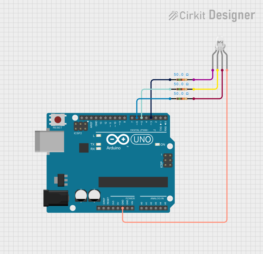
Circuit Documentation
Summary
This circuit utilizes an Arduino UNO microcontroller to control an RGB light (common cathode) through three PWM pins. The RGB light is connected to the Arduino via three resistors, which limit the current flowing to each color channel (Red, Green, Blue). The circuit is designed to create various lighting patterns by adjusting the brightness of each color channel based on the programmed logic in the Arduino code.
Component List
1. Arduino UNO
- Description: A microcontroller board based on the ATmega328P.
- Purpose: Acts as the main control unit for the circuit, executing the code to control the RGB light.
2. Resistor (50 Ohms)
- Description: A passive electrical component that resists the flow of current.
- Purpose: Used to limit the current to the RGB light's color channels, preventing damage to the LEDs.
3. Resistor (50 Ohms)
- Description: A passive electrical component that resists the flow of current.
- Purpose: Used to limit the current to the RGB light's green channel.
4. Resistor (50 Ohms)
- Description: A passive electrical component that resists the flow of current.
- Purpose: Used to limit the current to the RGB light's blue channel.
5. RGB Light (Common Cathode)
- Description: An LED component that contains red, green, and blue LEDs in a single package.
- Purpose: Produces various colors by mixing the intensities of the red, green, and blue channels.
Wiring Details
Arduino UNO
- GND connected to RGB Light (-)
Resistor (50 Ohms)
- pin1 connected to Arduino UNO D6
- pin2 connected to RGB Light (R)
Resistor (50 Ohms)
- pin1 connected to Arduino UNO D5
- pin2 connected to RGB Light (G)
Resistor (50 Ohms)
- pin1 connected to Arduino UNO D3
- pin2 connected to RGB Light (B)
Documented Code
// Arduino Uno RGB test on PWM pins: R=3, G=5, B=6
// Runs 3 patterns; set COMMON_ANODE = true for common-anode LEDs.

#include <math.h>

const uint8_t PIN_R = 3;
const uint8_t PIN_G = 5;
const uint8_t PIN_B = 6;

const bool COMMON_ANODE = false;
const unsigned long MODE_TIME = 8000;

unsigned long lastStep = 0;
unsigned long modeStart = 0;
uint8_t mode = 0;

// Mode 0: Hue wheel
float hue = 0.0f;

// Mode 1: Breathe palette
const uint8_t palette[][3] = {
  {255, 0, 0},
  {0, 255, 0},
  {0, 0, 255},
  {0, 255, 255},
  {255, 0, 255},
  {255, 255, 0},
  {255, 255, 255}
};
uint8_t palIdx = 0;
bool palDirUp = true;
uint8_t palLevel = 0;

// Mode 2: Random crossfade
uint8_t curR = 0, curG = 0, curB = 0;
uint8_t tgtR = 0, tgtG = 0, tgtB = 0;
unsigned long xfadeStart = 0;
const unsigned long XFADE_TIME = 2000;

// Utils
inline uint8_t maybeInvert(uint8_t v) {
  return COMMON_ANODE ? (uint8_t)(255 - v) : v;
}

void writeRGB(uint8_t r, uint8_t g, uint8_t b) {
  analogWrite(PIN_R, maybeInvert(r));
  analogWrite(PIN_G, maybeInvert(g));
  analogWrite(PIN_B, maybeInvert(b));
}

// HSV(0..360, 0..1, 0..1) to RGB(0..255)
void hsvToRgb(float H, float S, float V, uint8_t &r, uint8_t &g, uint8_t &b) {
  while (H < 0) H += 360;
  while (H >= 360) H -= 360;
  float C = V * S;
  float X = C * (1 - fabsf(fmodf(H / 60.0f, 2.0f) - 1));
  float m = V - C;
  float Rp, Gp, Bp;  // renamed to avoid Arduino macro B1

  if (H < 60)      { Rp = C; Gp = X; Bp = 0; }
  else if (H < 120){ Rp = X; Gp = C; Bp = 0; }
  else if (H < 180){ Rp = 0; Gp = C; Bp = X; }
  else if (H < 240){ Rp = 0; Gp = X; Bp = C; }
  else if (H < 300){ Rp = X; Gp = 0; Bp = C; }
  else             { Rp = C; Gp = 0; Bp = X; }

  r = (uint8_t)((Rp + m) * 255.0f + 0.5f);
  g = (uint8_t)((Gp + m) * 255.0f + 0.5f);
  b = (uint8_t)((Bp + m) * 255.0f + 0.5f);
}

void setup() {
  pinMode(PIN_R, OUTPUT);
  pinMode(PIN_G, OUTPUT);
  pinMode(PIN_B, OUTPUT);

  modeStart = millis();
  lastStep = millis();

  randomSeed(analogRead(A0));
  tgtR = random(256);
  tgtG = random(256);
  tgtB = random(256);
  xfadeStart = millis();
}

void loop() {
  unsigned long now = millis();

  if (now - modeStart >= MODE_TIME) {
    modeStart = now;
    mode = (mode + 1) % 3;
  }

  switch (mode) {
    case 0: { // Rainbow hue wheel
      if (now - lastStep >= 15) {
        lastStep = now;
        hue += 2.0f;
        if (hue >= 360.0f) hue -= 360.0f;
        uint8_t r, g, b;
        hsvToRgb(hue, 1.0f, 1.0f, r, g, b);
        writeRGB(r, g, b);
      }
    } break;

    case 1: { // Breathe through palette colors
      if (now - lastStep >= 8) {
        lastStep = now;
        if (palDirUp) {
          if (palLevel < 255) palLevel++;
          else palDirUp = false;
        } else {
          if (palLevel > 0) palLevel--;
          else {
            palDirUp = true;
            palIdx = (palIdx + 1) % (sizeof(palette) / sizeof(palette[0]));
          }
        }
        uint16_t r = (uint16_t)palette[palIdx][0] * palLevel / 255;
        uint16_t g = (uint16_t)palette[palIdx][1] * palLevel / 255;
        uint16_t b = (uint16_t)palette[palIdx][2] * palLevel / 255;
        writeRGB((uint8_t)r, (uint8_t)g, (uint8_t)b);
      }
    } break;

    case 2: { // Smooth random crossfades
      unsigned long elapsed = now - xfadeStart;
      if (elapsed >= XFADE_TIME) {
        curR = tgtR; curG = tgtG; curB = tgtB;
        tgtR = random(256);
        tgtG = random(256);
        tgtB = random(256);
        xfadeStart = now;
        elapsed = 0;
      }
      float t = (float)elapsed / (float)XFADE_TIME;
      float u = t * t * (3 - 2 * t);
      uint8_t r = (uint8_t)(curR + (tgtR - curR) * u + 0.5f);
      uint8_t g = (uint8_t)(curG + (tgtG - curG) * u + 0.5f);
      uint8_t b = (uint8_t)(curB + (tgtB - curB) * u + 0.5f);
      writeRGB(r, g, b);
      delay(5);
    } break;
  }
}
This documentation provides a comprehensive overview of the circuit, detailing the components used, their connections, and the code that drives the functionality of the RGB light.