
Circuit Documentation
Summary
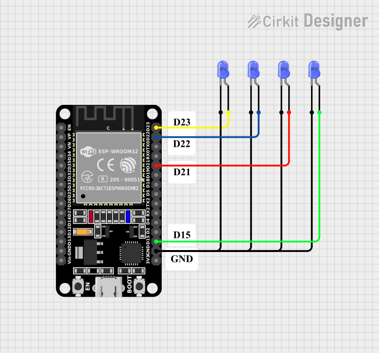
This document provides a detailed overview of a circuit that includes an ESP32 microcontroller and four blue LEDs. The ESP32 controls the LEDs by driving their anodes through its GPIO pins, while all LED cathodes are connected to the ground (GND) pin of the ESP32.
Component List
ESP32 (30 pin)
- Description: A versatile microcontroller with built-in Wi-Fi and Bluetooth capabilities.
- Pins: EN, VP, VN, D34, D35, D32, D33, D25, D26, D27, D14, D12, D13, GND, Vin, D23, D22, TX0, RX0, D21, D19, D18, D5, TX2, RX2, D4, D2, D15, 3V3
LED: Two Pin (blue)
- Description: A blue light-emitting diode.
- Pins: cathode, anode
Comment
- Description: Placeholder for comments or notes in the circuit.
- Pins: None
Wiring Details
ESP32 (30 pin)
- D23: Connected to the anode of the first blue LED.
- D22: Connected to the anode of the second blue LED.
- D21: Connected to the anode of the third blue LED.
- D15: Connected to the anode of the fourth blue LED.
- GND: Connected to the cathodes of all four blue LEDs.
LED: Two Pin (blue)
First LED
- Anode: Connected to D23 of the ESP32.
- Cathode: Connected to GND of the ESP32.
Second LED
- Anode: Connected to D22 of the ESP32.
- Cathode: Connected to GND of the ESP32.
Third LED
- Anode: Connected to D21 of the ESP32.
- Cathode: Connected to GND of the ESP32.
Fourth LED
- Anode: Connected to D15 of the ESP32.
- Cathode: Connected to GND of the ESP32.
Comment
- No electrical connections.
Code
No code is provided for this circuit.