
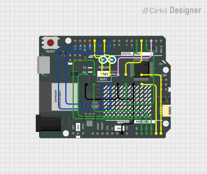
Circuit Documentation
Summary
This document provides a detailed overview of a circuit that interfaces an Arduino UNO R4 WiFi with a 64x32 LED Matrix. The Arduino controls the LED Matrix, allowing for dynamic display of colors and patterns. The document includes a component list, wiring details, and the embedded code used in the microcontroller.
Component List
LED Matrix 64x32
- Description: A 64x32 LED matrix display.
- Pins: R1, B1, R2, B2, A, C, CLK, OE, G1, GND, G2, B, D, LAT
Arduino UNO R4 WiFi
- Description: A microcontroller board based on the ATmega328P, with built-in WiFi capabilities.
- Pins: OFF, GND, VRTC, IIC0_SCL, IIC0_SDA, 3V3, GPIO 41, GPIO 0, GPIO 42, GPIO 43, GPIO 44, BOOT, IOREF, RESET, 5V, VIN, A0, A1, A2, A3, A4, A5, RSPCKA, CIPO, COPI, D0/RX, D1/TX, D2, D3, D4, D5, D6, D7, D8, D9, D10, D11, D12, D13, AREF, SDA, SCL
Wiring Details
LED Matrix 64x32
- R1 connected to Arduino UNO R4 WiFi A5
- B1 connected to Arduino UNO R4 WiFi D5
- R2 connected to Arduino UNO R4 WiFi D4
- B2 connected to Arduino UNO R4 WiFi D2
- A connected to Arduino UNO R4 WiFi D11
- C connected to Arduino UNO R4 WiFi D13
- CLK connected to Arduino UNO R4 WiFi A1
- OE connected to Arduino UNO R4 WiFi A3
- G1 connected to Arduino UNO R4 WiFi A4
- GND connected to Arduino UNO R4 WiFi GND
- G2 connected to Arduino UNO R4 WiFi D3
- B connected to Arduino UNO R4 WiFi D12
- D connected to Arduino UNO R4 WiFi D10
- LAT connected to Arduino UNO R4 WiFi A2
Arduino UNO R4 WiFi
- A5 connected to LED Matrix 64x32 R1
- D5 connected to LED Matrix 64x32 B1
- D4 connected to LED Matrix 64x32 R2
- D2 connected to LED Matrix 64x32 B2
- D11 connected to LED Matrix 64x32 A
- D13 connected to LED Matrix 64x32 C
- A1 connected to LED Matrix 64x32 CLK
- A3 connected to LED Matrix 64x32 OE
- A4 connected to LED Matrix 64x32 G1
- GND connected to LED Matrix 64x32 GND
- D3 connected to LED Matrix 64x32 G2
- D12 connected to LED Matrix 64x32 B
- D10 connected to LED Matrix 64x32 D
- A2 connected to LED Matrix 64x32 LAT
Code Documentation
Arduino UNO R4 WiFi Code
#include <Panel.h>

// which cable goes where
#define RA 14 // register selector a
#define RB 15 // register selector b
#define RC 16 // register selector c
#define RD 18 // register selector d
#define RF 2 // red first byte
#define RS 5 // red second byte
#define BF 4 // blue first byte
#define BS 7 // blue second byte
#define GF 3 // green first byte
#define GS 6 // green second byte
#define LAT 17 // data latch
#define CLK 8 // clock signal
#define OE 9 // output enable

Panel panel(32, 64, false);

void setup() {
  // put your setup code here, to run once:
}

void loop() {
  // this example iterates through all available colors in the panel
  for (long i = 0; i < 26000; i++) {
    panel.fillScreenColor(i / 1000); // changes after some time
  }
  /*
  |||ALL COLORS|||
  RED,
  GREEN,
  BLUE,
  WHITE,
  BLACK,
  PURPLE,
  YELLOW,
  CYAN,
  LIGHTRED,
  LIGHTGREEN,
  LIGHTBLUE,
  LIGHTWHITE,
  LIGHTCYAN,
  DARKYELLOW,
  LIGHTPURPLE,
  LIGHTYELLOW,
  TURQUOISE,
  PINK,
  DARKPURPLE,
  BRIGHTGREEN,
  BRIGHTCYAN,
  MEDIUMGREEN,
  DEEPPURPLE,
  OCEANBLUE,
  FLESH,
  LIGHTPINK,
  */
}
This code initializes the LED panel and iterates through a range of colors, displaying them on the LED matrix. The Panel library is used to manage the display, and various pins on the Arduino are defined to control the LED matrix.