Cirkit Designer
Your all-in-one circuit design IDE
Home /
Project Documentation
Arduino UNO Controlled Dual Fan System with LCD Feedback
Circuit Documentation
Summary
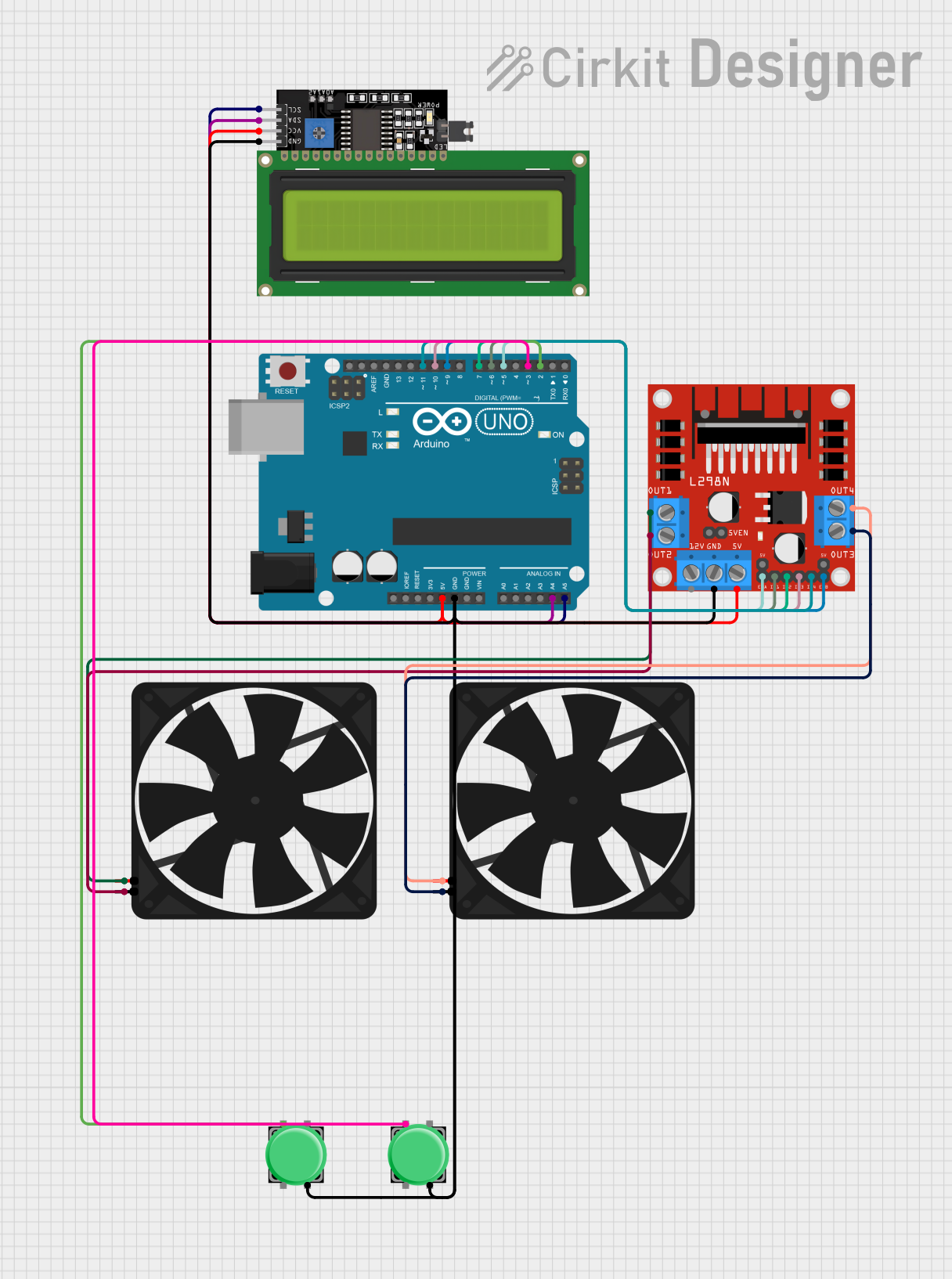
This circuit is designed to control two fans using an Arduino UNO microcontroller. It includes pushbuttons for user input, an LCD display for feedback, and an L298N DC motor driver to control the fan speeds and directions. The Arduino UNO is programmed to respond to button presses to change the state of the fans, which can rotate clockwise, counterclockwise, or stop. The LCD display provides a visual indication of the current state of each fan.
Component List
Arduino UNO
- Microcontroller board based on the ATmega328P
- Provides digital and analog I/O pins
- Used for controlling the overall logic of the circuit
Fan
- Two instances of a simple DC fan
- Powered by 5V and controlled by the L298N motor driver
Pushbutton
- Two instances of a pushbutton switch
- Used to provide user input to the Arduino UNO
LCD Display 16x4 I2C
- An alphanumeric liquid crystal display with I2C interface
- Displays the status of the fans
L298N DC Motor Driver
- A dual H-bridge motor driver
- Controls the direction and speed of the fans
Wiring Details
Arduino UNO
5VandGNDare used to power the L298N motor driver and the LCD display.A4 (SDA)andA5 (SCL)are connected to the LCD display for I2C communication.- Digital pins
D5,D6,D7,D9,D10, andD11are connected to the L298N motor driver to control the fans. - Digital pins
D2andD3are connected to the pushbuttons.
Fan
- Each fan has a
5VandGNDconnection, which are controlled by the L298N motor driver.
Pushbutton
- Each pushbutton has one pin connected to
GNDand another pin connected to a digital pin on the Arduino UNO (D2orD3).
LCD Display 16x4 I2C
VCCis connected to the5Voutput from the Arduino UNO.GNDis connected to the ground of the Arduino UNO.SDAandSCLare connected toA4andA5on the Arduino UNO for I2C communication.
L298N DC Motor Driver
5VandGNDare connected to the Arduino UNO for power.IN1,IN2,IN3,IN4,ENA, andENBare connected to the Arduino UNO digital pins for control signals.OUT1,OUT2,OUT3, andOUT4are connected to the fans to control their operation.
Documented Code
#include <Wire.h>
#include <LiquidCrystal_I2C.h>

// LCD initialization
LiquidCrystal_I2C lcd(0x27, 16, 2);

// Pin assignments
const int button1Pin = 2;
const int button2Pin = 3;
const int fan1EnablePin = 5;
const int fan1In1Pin = 6;
const int fan1In2Pin = 7;
const int fan2EnablePin = 9;
const int fan2In1Pin = 10;
const int fan2In2Pin = 11;

// Variables for button states
int button1State = 0;
int button2State = 0;
int button1PressCount = 0;
int button2PressCount = 0;
unsigned long lastDebounceTime1 = 0;
unsigned long lastDebounceTime2 = 0;
unsigned long debounceDelay = 50;

void setup() {
  // Initialize pins
  pinMode(button1Pin, INPUT_PULLUP);
  pinMode(button2Pin, INPUT_PULLUP);
  pinMode(fan1EnablePin, OUTPUT);
  pinMode(fan1In1Pin, OUTPUT);
  pinMode(fan1In2Pin, OUTPUT);
  pinMode(fan2EnablePin, OUTPUT);
  pinMode(fan2In1Pin, OUTPUT);
  pinMode(fan2In2Pin, OUTPUT);

  // Initialize the LCD
  lcd.begin();
  lcd.backlight();
  lcd.clear();
  lcd.setCursor(0, 0);
  lcd.print("Fan Control");
  delay(1000);
  lcd.clear();
}

void loop() {
  int reading1 = digitalRead(button1Pin);
  int reading2 = digitalRead(button2Pin);

  if (reading1 == LOW && (millis() - lastDebounceTime1 > debounceDelay)) {
    lastDebounceTime1 = millis();
    button1PressCount++;
    if (button1PressCount > 3) button1PressCount = 1;
    controlFan1(button1PressCount);
  }

  if (reading2 == LOW && (millis() - lastDebounceTime2 > debounceDelay)) {
    lastDebounceTime2 = millis();
    button2PressCount++;
    if (button2PressCount > 3) button2PressCount = 1;
    controlFan2(button2PressCount);
  }
}

void controlFan1(int pressCount) {
  switch (pressCount) {
    case 1:
      lcd.clear();
      lcd.setCursor(0, 0);
      lcd.print("Fan1: Clockwise");
      digitalWrite(fan1In1Pin, HIGH);
      digitalWrite(fan1In2Pin, LOW);
      analogWrite(fan1EnablePin, 255);
      break;
    case 2:
      lcd.clear();
      lcd.setCursor(0, 0);
      lcd.print("Fan1: Counter");
      digitalWrite(fan1In1Pin, LOW);
      digitalWrite(fan1In2Pin, HIGH);
      analogWrite(fan1EnablePin, 255);
      break;
    case 3:
      lcd.clear();
      lcd.setCursor(0, 0);
      lcd.print("Fan1: Stop");
      analogWrite(fan1EnablePin, 0);
      break;
  }
}

void controlFan2(int pressCount) {
  switch (pressCount) {
    case 1:
      lcd.clear();
      lcd.setCursor(0, 1);
      lcd.print("Fan2: Counter");
      digitalWrite(fan2In1Pin, LOW);
      digitalWrite(fan2In2Pin, HIGH);
      analogWrite(fan2EnablePin, 255);
      break;
    case 2:
      lcd.clear();
      lcd.setCursor(0, 1);
      lcd.print("Fan2: Clockwise");
      digitalWrite(fan2In1Pin, HIGH);
      digitalWrite(fan2In2Pin, LOW);
      analogWrite(fan2EnablePin, 255);
      break;
    case 3:
      lcd.clear();
      lcd.setCursor(0, 1);
      lcd.print("Fan2: Stop");
      analogWrite(fan2EnablePin, 0);
      break;
  }
}
This code is responsible for the operation of the fans and the display of their status on the LCD. It includes debouncing for the pushbuttons and functions to control the fans based on the button presses.