Cirkit Designer
Your all-in-one circuit design IDE
Home /
Project Documentation
Arduino UNO Controlled Interactive Display with Keypad Input and Motor Feedback

Circuit Documentation
Summary
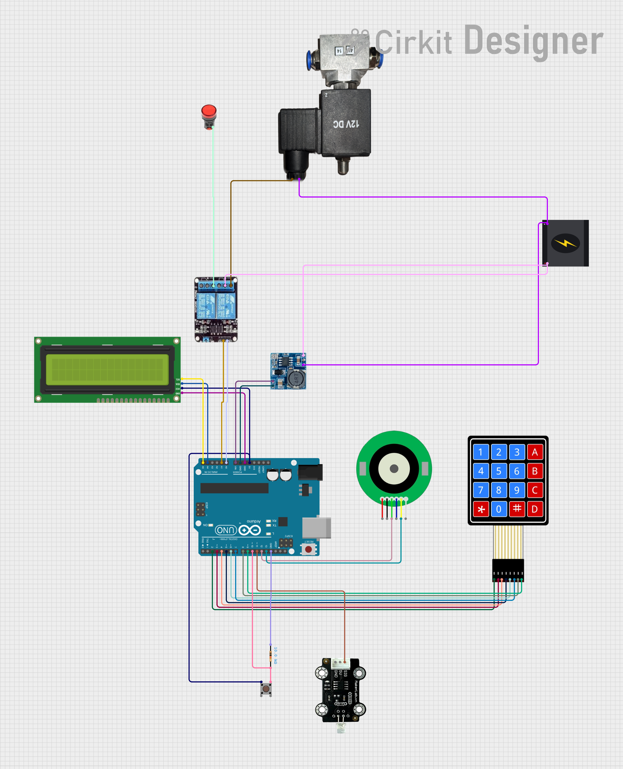
This circuit is designed to interface an Arduino UNO with a variety of components including an I2C LCD 16x2 Screen, a 4x4 Membrane Matrix Keypad, a 12V DC Motor Encoder, a Pushbutton, a Resistor, an MKE-S03 Photo Diode Light Sensor, a 12V Pneumatic Solenoid Valve, a 2-Channel Relay, a Red Lamp, and a Step-Down Module. The circuit is powered by a 240V Power Source. The Arduino UNO is programmed to interact with these components, displaying information on the LCD, reading inputs from the keypad and the photo diode light sensor, controlling the motor encoder, and activating the pneumatic solenoid valve and lamp via the relays.
Component List
Arduino UNO
- Microcontroller board based on the ATmega328P
- Provides digital and analog I/O pins
- Features serial communication capabilities
I2C LCD 16x2 Screen
- Alphanumeric liquid crystal display
- Communicates with the Arduino via I2C protocol
- Displays text and numbers
4X4 Membrane Matrix Keypad
- Input device with 16 buttons arranged in a 4x4 grid
- Provides user interface for inputting commands
12V DC Motor Encoder
- A motor with an integrated encoder for position feedback
- Used for precise control of rotational movement
Pushbutton
- A simple switch mechanism for control of a device
- Used as a manual input or trigger
Resistor (10k Ohms)
- Passive two-terminal electrical component
- Implements electrical resistance as a circuit element
MKE-S03 Photo Diode Light Sensor
- A sensor that detects light intensity
- Converts light into an electrical signal
12V Pneumatic Solenoid Valve
- An electromechanically operated valve
- Controlled by an electric current through a solenoid
2-Channel Relay
- An electrically operated switch
- Allows the Arduino to control higher power circuits
Lamp Red
- A simple red indicator lamp
- Used for visual signaling
240V Power Source
- Provides the main electrical power for the circuit
- Supplies 240V AC power
Step-Down Module
- Converts higher voltage to a lower voltage
- Provides 5V and 12V outputs from a 24V input
Wiring Details
Arduino UNO
5Vconnected to I2C LCD Screen VCC (5V) and Pushbutton Pin 1 (in)GNDconnected to I2C LCD Screen GND, Resistor pin1, and Step-Down Module 5v OUT-Vinconnected to Step-Down Module 5v OUT+A0connected to 2ch Relay IN2A1connected to 2ch Relay IN1A4connected to I2C LCD Screen SDAA5connected to I2C LCD Screen SCLD2toD9connected to 4X4 Membrane Matrix Keypad R1 to C4 respectivelyD10connected to Resistor pin2 and Pushbutton Pin 3 (out)D11connected to MKE-S03 Photo Diode Light Sensor SIGD12connected to 12V DC Motor Encoder AD13connected to 12V DC Motor Encoder B
I2C LCD 16x2 Screen
VCC (5V)andGNDconnected to Arduino UNOSDAandSCLconnected to Arduino UNO A4 and A5 respectively
4X4 Membrane Matrix Keypad
R1toR4connected to Arduino UNO D2 to D5 respectivelyC1toC4connected to Arduino UNO D6 to D9 respectively
12V DC Motor Encoder
AandBconnected to Arduino UNO D12 and D13 respectively
Pushbutton
Pin 1 (in)connected to Arduino UNO 5VPin 3 (out)connected to Arduino UNO D10
Resistor (10k Ohms)
pin1connected to Arduino UNO GNDpin2connected to Arduino UNO D10 and Pushbutton Pin 3 (out)
MKE-S03 Photo Diode Light Sensor
SIGconnected to Arduino UNO D11
2-Channel Relay
IN1andIN2connected to Arduino UNO A0 and A1 respectivelyNOconnected to 12V Pneumatic Solenoid Valve GND and Lamp Red -COMconnected to 240V Power Source Live
Step-Down Module
5v OUT+and5v OUT-connected to Arduino UNO Vin and GND respectively24v IN+connected to 240V Power Source Live
240V Power Source
Neutralconnected to 12V Pneumatic Solenoid Valve VCCLiveconnected to Step-Down Module 24v IN+ and 2ch Relay COM
Documented Code
// dupodmuch 1.2
#include <Wire.h>
#include <LiquidCrystal_I2C.h>
#include <Keypad.h>
#include <Encoder.h>

// LCD setup
LiquidCrystal_I2C lcd(0x27, 16, 2);

// Keypad setup
const byte ROWS = 4; // Four rows
const byte COLS = 4; // Four columns
char keys[ROWS][COLS] = {
  {'1','2','3','A'},
  {'4','5','6','B'},
  {'7','8','9','C'},
  {'*','0','#','D'}
};
byte rowPins[ROWS] = {2, 3, 4, 5}; // Connect to the row pinouts of the keypad
byte colPins[COLS] = {6, 7, 8, 9}; // Connect to the column pinouts of the keypad
Keypad keypad = Keypad(makeKeymap(keys), rowPins, colPins, ROWS, COLS);

// Encoder setup
Encoder myEnc(12, 13);

// Pin definitions
const int buttonPin = 10;
const int photocellPin = 11;
const int relay1Pin = A0;
const int relay2Pin = A1;

// Parameters
float droga = 520.9; // Default distance in mm per 1000 encoder pulses
int licznik = 0; // Counter for interruptions
int cykl = 2; // Default cycle count
float dmuchstart = 20.0; // Start blowing at 20mm
float dmuchstop = 80.0; // Stop blowing at 80mm
float zero = 0.0; // Zero position
float zator = 520.9; // Default blockage distance

// State variables
long encoderPosition = 0;
bool relay1State = false;
bool relay2State = false;

void setup() {
  // Initialize LCD
  lcd.begin();
  lcd.backlight();
  lcd.print("Dupodmuch 1.2");
  delay(3000);
  lcd.clear();

  // Initialize pins
  pinMode(buttonPin, INPUT);
  pinMode(photocellPin, INPUT);
  pinMode(relay1Pin, OUTPUT);
  pinMode(relay2Pin, OUTPUT);

  // Initialize relays
  digitalWrite(relay1Pin, HIGH); // Relay 1 off
  digitalWrite(relay2Pin, HIGH); // Relay 2 off
}

void loop() {
  // Read encoder position
  long newPosition = myEnc.read();
  if (newPosition != encoderPosition) {
    encoderPosition = newPosition;
    // Update display with encoder position
    lcd.setCursor(0, 1);
    lcd.print("Pos: ");
    lcd.print(encoderPosition);
  }

  // Read keypad input
  char key = keypad.getKey();
  if (key) {
    handleKeypadInput(key);
  }

  // Read photocell state
  int photocellState = digitalRead(photocellPin);
  if (photocellState == LOW) {
    licznik++;
    lcd.setCursor(0, 1);
    lcd.print("Licznik: ");
    lcd.print(licznik);
  }

  // Check for relay 1 activation
  if (encoderPosition >= dmuchstart && encoderPosition <= dmuchstop) {
    digitalWrite(relay1Pin, LOW); // Activate relay 1
    relay1State = true;
  } else {
    digitalWrite(relay1Pin, HIGH); // Deactivate relay 1
    relay1State = false;
  }

  // Check for relay 2 activation
  if (encoderPosition >= zator) {
    digitalWrite(relay2Pin, LOW); // Activate relay 2
    relay2State = true;
  }

  // Check for button press
  if (digitalRead(buttonPin) == LOW) {
    digitalWrite(relay1Pin, LOW); // Manually activate relay 1
    relay1State = true;