
Arduino Mega 2560-Based Smart Home Automation System with LCD Display and Sensor Integration
View and Edit Project In Cirkit Designer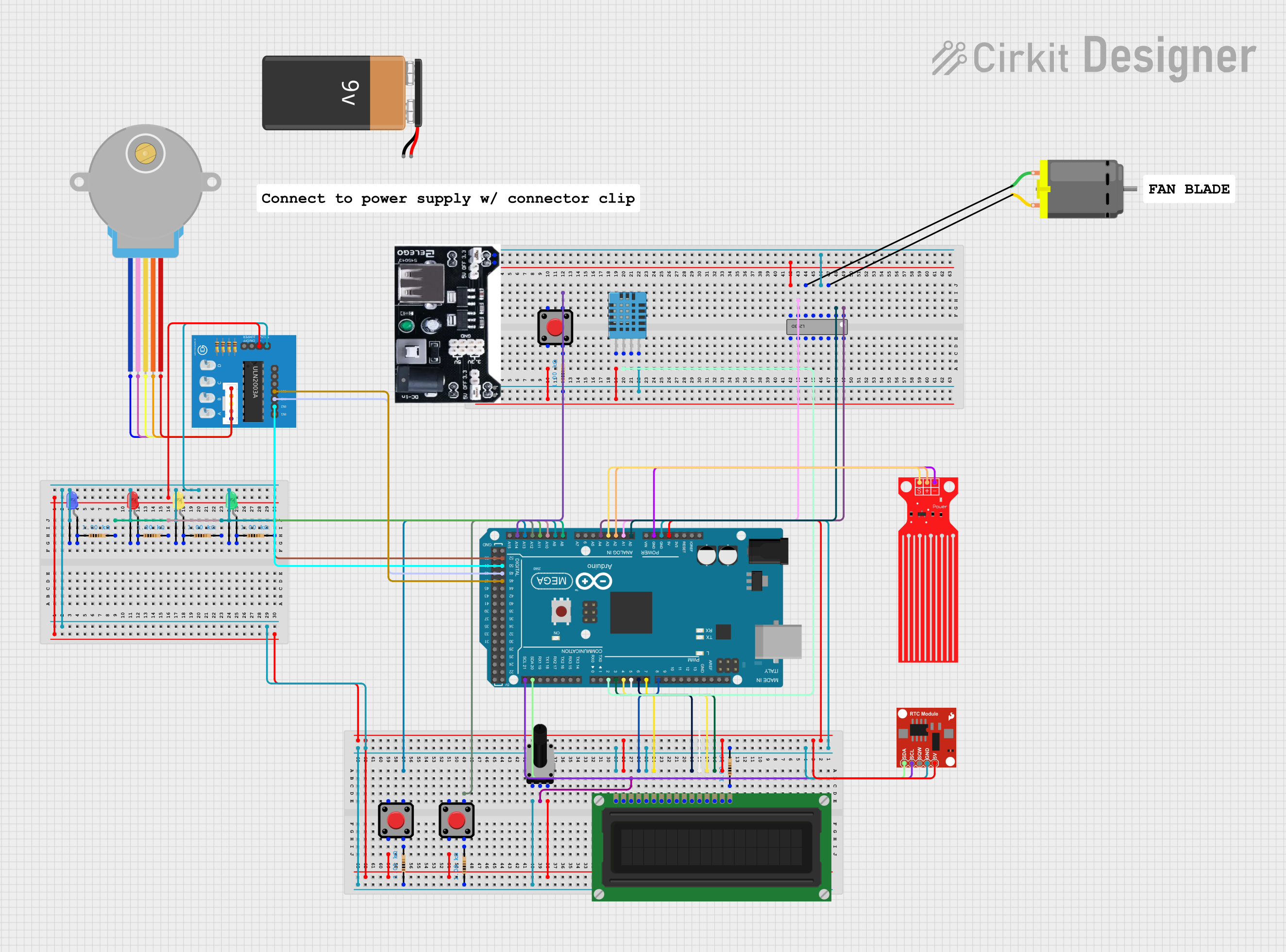
Circuit Documentation
Summary
This circuit involves an Arduino Mega 2560 microcontroller interfacing with various components including an LCD display, pushbuttons, LEDs, a rotary potentiometer, a stepper motor, a temperature and humidity sensor, a real-time clock module, a DC motor, and a water level sensor. The circuit is designed to demonstrate basic input/output operations, motor control, and sensor data acquisition.
Component List
Arduino Mega 2560
- Description: A microcontroller board based on the ATmega2560.
- Pins: IOREF, RESET, 3V3, 5V, GND, VIN, A0-A15, D0-D53, AREF, SDA, SCL
LCD Display (16 pin)
- Description: A 16x2 character LCD display.
- Pins: VSS, VDD, VO, RS, R_W, E, DB0-DB7, A, K
Rotary Potentiometer
- Description: A variable resistor used to adjust voltage.
- Pins: leg1, wiper, leg2
- Properties: Resistance: 10k Ohms
Pushbutton
- Description: A simple pushbutton switch.
- Pins: Pin 1, Pin 2, Pin 3, Pin 4
Resistor
- Description: A passive electrical component that implements electrical resistance.
- Pins: pin1, pin2
- Properties: Resistance: 1k Ohms
LED: Two Pin (blue)
- Description: A blue light-emitting diode.
- Pins: cathode, anode
LED: Two Pin (red)
- Description: A red light-emitting diode.
- Pins: cathode, anode
LED: Two Pin (yellow)
- Description: A yellow light-emitting diode.
- Pins: cathode, anode
LED: Two Pin (green)
- Description: A green light-emitting diode.
- Pins: cathode, anode
28BYJ-48 Stepper Motor
- Description: A small stepper motor.
- Pins: BLUE, PINK, YELLOW, ORANGE, RED
ULN2003A breakout board
- Description: A Darlington transistor array used to drive the stepper motor.
- Pins: In 1-In 7, 0V, +5V, ON/OFF jumper switch, BLUE wire, PINK wire, YELLOW wire, ORANGE wire, RED wire
Power mb V2
- Description: A power supply module.
- Pins: -, +, DC-ln
DHT11 Humidity and Temperature Sensor
- Description: A sensor for measuring temperature and humidity.
- Pins: VDD, DATA, NULL, GND
L293D
- Description: A quadruple high-current half-H driver.
- Pins: Enable 1,2, Input 1, Output 1, GND, Output 2, Input 2, VCC2, VCC1, Input 4, Output 4, Output 3, Input 3, Enable 3,4
DC Motor
- Description: A simple DC motor.
- Pins: pin 1, pin 2
Water Level Sensor
- Description: A sensor for detecting water levels.
- Pins: SIG, VCC, GND
Real Time Clock Module - DS1307 RTC Breakout Board
- Description: A real-time clock module.
- Pins: 5V, GND, SQW, SCL, SDA
9V Battery
- Description: A 9V battery for power supply.
- Pins: -, +
Wiring Details
Arduino Mega 2560
- 5V: Connected to VDD and A of LCD Display, 5V of Real Time Clock Module, leg2 of Rotary Potentiometer, Pin 2 of two Pushbuttons, and +5V of ULN2003A breakout board.
- GND: Connected to VSS and R_W of LCD Display, GND of Real Time Clock Module, leg1 of Rotary Potentiometer, cathode of four LEDs, 0V of ULN2003A breakout board, and GND of Water Level Sensor.
- D2 PWM: Connected to DATA of DHT11 Humidity and Temperature Sensor.
- D3 PWM: Connected to DB7 of LCD Display.
- D4 PWM: Connected to DB6 of LCD Display.
- D5 PWM: Connected to DB5 of LCD Display.
- D6 PWM: Connected to DB4 of LCD Display.
- D7 PWM: Connected to E of LCD Display.
- D8 PWM: Connected to RS of LCD Display.
- D21/SCL: Connected to SCL of Real Time Clock Module.
- D20/SDA: Connected to SDA of Real Time Clock Module.
- D52: Connected to In 1 of ULN2003A breakout board.
- D50: Connected to In 2 of ULN2003A breakout board.
- D48: Connected to In 3 of ULN2003A breakout board.
- D46: Connected to In 4 of ULN2003A breakout board.
- A0: Connected to Input 1 of L293D.
- A1: Connected to Input 2 of L293D.
- A2: Connected to VCC of Water Level Sensor.
- A3: Connected to SIG of Water Level Sensor.
- A4: Connected to Enable 1,2 of L293D.
- A8: Connected to pin2 of a Resistor.
- A9: Connected to pin2 of a Resistor.
- A10: Connected to pin2 of a Resistor.
- A11: Connected to pin2 of a Resistor.
- A12: Connected to Pin 4 of a Pushbutton.
- A13: Connected to Pin 4 of a Pushbutton.
- A14: Connected to Pin 4 of a Pushbutton.
LCD Display (16 pin)
- VSS: Connected to GND of Arduino Mega 2560.
- VDD: Connected to 5V of Arduino Mega 2560.
- VO: Connected to wiper of Rotary Potentiometer.
- RS: Connected to D8 PWM of Arduino Mega 2560.
- R_W: Connected to GND of Arduino Mega 2560.
- E: Connected to D7 PWM of Arduino Mega 2560.
- DB4: Connected to D6 PWM of Arduino Mega 2560.
- DB5: Connected to D5 PWM of Arduino Mega 2560.
- DB6: Connected to D4 PWM of Arduino Mega 2560.
- DB7: Connected to D3 PWM of Arduino Mega 2560.
- A: Connected to 5V of Arduino Mega 2560.
- K: Connected to pin1 of a Resistor.
Rotary Potentiometer
- leg1: Connected to GND of Arduino Mega 2560.
- wiper: Connected to VO of LCD Display.
- leg2: Connected to 5V of Arduino Mega 2560.
Pushbutton
- Pin 2: Connected to 5V of Arduino Mega 2560.
- Pin 4: Connected to A12, A13, and A14 of Arduino Mega 2560.
- Pin 3: Connected to pin2 of Resistors.
Resistor
- pin1: Connected to K of LCD Display, anode of four LEDs, and Pin 3 of Pushbuttons.
- pin2: Connected to A8, A9, A10, A11, and Pin 3 of Pushbuttons.
LED: Two Pin (blue)
- cathode: Connected to GND of Arduino Mega 2560.
- anode: Connected to pin1 of a Resistor.
LED: Two Pin (red)
- cathode: Connected to GND of Arduino Mega 2560.
- anode: Connected to pin1 of a Resistor.
LED: Two Pin (yellow)
- cathode: Connected to GND of Arduino Mega 2560.
- anode: Connected to pin1 of a Resistor.
LED: Two Pin (green)
- cathode: Connected to GND of Arduino Mega 2560.
- anode: Connected to pin1 of a Resistor.
28BYJ-48 Stepper Motor
- BLUE: Connected to BLUE wire of ULN2003A breakout board.
- PINK: Connected to PINK wire of ULN2003A breakout board.
- YELLOW: Connected to YELLOW wire of ULN2003A breakout board.
- ORANGE: Connected to ORANGE wire of ULN2003A breakout board.
- RED: Connected to RED wire of ULN2003A breakout board.
ULN2003A breakout board
- In 1: Connected to D52 of Arduino Mega 2560.
- In 2: Connected to D50 of Arduino Mega 2560.
- In 3: Connected to D48 of Arduino Mega 2560.
- In 4: Connected to D