
Arduino Mega 2560 Controlled Ultrasonic Sensor Array with Multi-Color LED Indicators
View and Edit Project In Cirkit Designer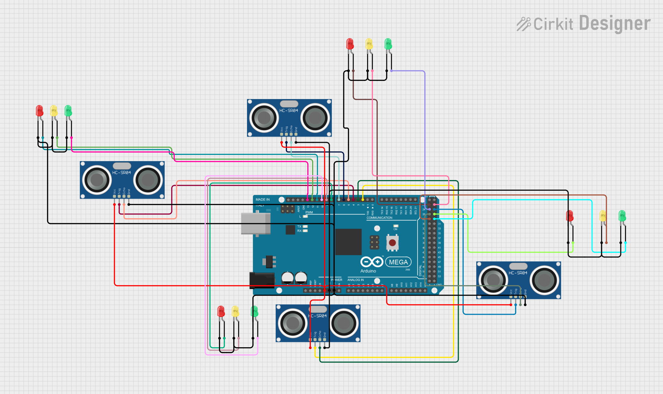
Circuit Documentation
Summary
The circuit in question is designed to interface an array of LEDs and multiple HC-SR04 Ultrasonic Sensors with an Arduino Mega 2560 microcontroller. The HC-SR04 sensors are used to measure distances via ultrasonic waves, and the LEDs serve as indicators. The Arduino Mega 2560 controls the sensors and LEDs, and it also handles serial communication to receive data and check its validity using a parity bit.
Component List
Microcontroller
- Arduino Mega 2560: A microcontroller board based on the ATmega2560, with a wide range of digital and analog I/O pins.
Sensors
- HC-SR04 Ultrasonic Sensor: An ultrasonic distance sensor that provides 2cm to 400cm of non-contact measurement functionality with a ranging accuracy of up to 3mm.
Indicators
- LED: Two Pin (red): A basic red LED for indication purposes.
- LED: Two Pin (green): A basic green LED for indication purposes.
- LED: Two Pin (yellow): A basic yellow LED for indication purposes.
Wiring Details
Arduino Mega 2560
- 5V connected to VCC of all HC-SR04 Ultrasonic Sensors.
- GND connected to GND of all HC-SR04 Ultrasonic Sensors and cathodes of all LEDs.
- Digital Pins (D2-D13, D22-D29) connected to TRIG and ECHO pins of HC-SR04 Ultrasonic Sensors and anodes of LEDs.
HC-SR04 Ultrasonic Sensors
- VCC connected to 5V on Arduino Mega 2560.
- GND connected to GND on Arduino Mega 2560.
- TRIG connected to various digital pins on Arduino Mega 2560 for triggering the ultrasonic pulse.
- ECHO connected to various digital pins on Arduino Mega 2560 for receiving the echo pulse.
LEDs (Red, Green, Yellow)
- Cathode (-) connected to GND on Arduino Mega 2560.
- Anode (+) connected to various digital pins on Arduino Mega 2560.
Documented Code
File: sketch.ino
void setup() {
  Serial.begin(9600);  // Initialize Serial communication for receiver
}

void loop() {
  if (Serial.available() > 0) { // Check if data is received
    String receivedData = Serial.readStringUntil('\n'); // Read data
    receivedData.trim(); // Remove any unwanted trailing characters
    Serial.println("Received Data: " + receivedData);

    if (isValid(receivedData)) {
      Serial.println("Data is valid!");
    } else {
      Serial.println("Error detected in the received data!");
    }
  }
}

// Function to check the validity of received data using parity bit
bool isValid(String data) {
  int onesCount = 0;
  for (int i = 0; i < data.length() - 1; i++) { // Exclude the parity bit
    if (data[i] == '1') onesCount++;
  }
  char expectedParity = (onesCount % 2 == 0) ? '0' : '1'; // Calculate expected parity
  return data[data.length() - 1] == expectedParity; // Compare parity bit
}
File: documentation.txt
The second file, documentation.txt, does not contain any code. It is likely intended to be a placeholder for additional documentation or notes related to the project.