
Arduino UNO Controlled LED with Potentiometer Brightness Adjustment
View and Edit Project In Cirkit Designer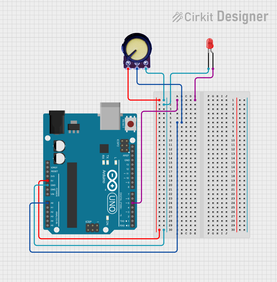
Circuit Documentation
Summary
This circuit consists of an Arduino UNO microcontroller, a red LED, and a potentiometer. The Arduino UNO controls the LED and reads the potentiometer's output. The LED is connected to a digital pin on the Arduino, and the potentiometer is connected to an analog input pin.
Component List
LED: Two Pin (red)
- Description: A red LED with two pins: anode and cathode.
- Pins:
- Anode
- Cathode
Arduino UNO
- Description: A microcontroller board based on the ATmega328P.
- Pins:
- UNUSED
- IOREF
- Reset
- 3.3V
- 5V
- GND
- Vin
- A0
- A1
- A2
- A3
- A4
- A5
- SCL
- SDA
- AREF
- D13
- D12
- D11
- D10
- D9
- D8
- D7
- D6
- D5
- D4
- D3
- D2
- D1
- D0
Potentiometer
- Description: A three-terminal resistor with a sliding or rotating contact that forms an adjustable voltage divider.
- Pins:
- GND
- Output
- VCC
Wiring Details
LED: Two Pin (red)
- Anode: Connected to D5 on the Arduino UNO.
- Cathode: Connected to GND on the Arduino UNO and VCC on the Potentiometer.
Arduino UNO
- D5: Connected to the anode of the LED.
- 5V: Connected to GND on the Potentiometer.
- GND: Connected to the cathode of the LED and VCC on the Potentiometer.
- A0: Connected to the output of the Potentiometer.
Potentiometer
- GND: Connected to 5V on the Arduino UNO.
- Output: Connected to A0 on the Arduino UNO.
- VCC: Connected to the cathode of the LED and GND on the Arduino UNO.
Documented Code
Arduino UNO Code
void setup() {
  // put your setup code here, to run once:

}

void loop() {
  // put your main code here, to run repeatedly:

}
This code is a basic template for the Arduino UNO. The setup function is where you initialize your settings, and the loop function is where the main code runs repeatedly.
Additional Documentation
This section is reserved for any additional documentation or notes related to the code or circuit.