ESP32 and NRF24L01 Wireless Data Receiver
Circuit Documentation
Summary of the Circuit
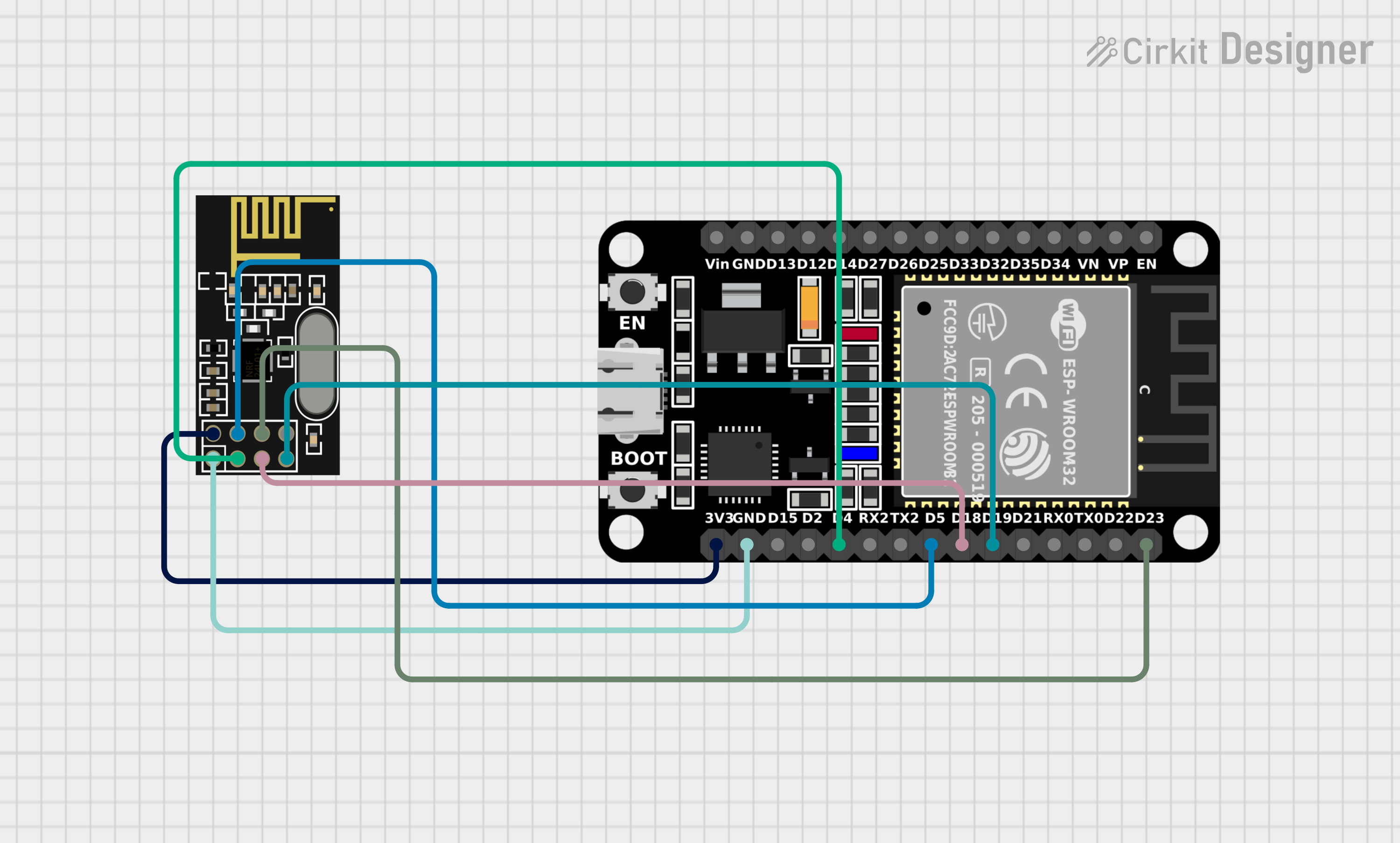
This circuit integrates an NRF24L01 module with an ESP32 microcontroller to establish a wireless communication link. The NRF24L01 is a 2.4GHz wireless transceiver that interfaces with the ESP32 through SPI (Serial Peripheral Interface). The ESP32 is programmed to receive data from the NRF24L01 module and output the received data to the Serial Monitor. The circuit is powered by a 3.3V supply, which is common to both the ESP32 and the NRF24L01 to ensure compatible logic levels.
Component List
NRF24L01
- Description: 2.4GHz Wireless Transceiver Module
- Pins: IRQ (not used), MOSI, CSN, VCC (3V), GND, CE, SCK, MISO
- Purpose: To transmit and receive data wirelessly.
ESP32 (30 pin)
- Description: 32-bit Microcontroller with Wi-Fi and Bluetooth capabilities
- Pins: EN, VP, VN, D34, D35, D32, D33, D25, D26, D27, D14, D12, D13, GND, Vin, D23, D22, TX0, RX0, D21, D19, D18, D5, TX2, RX2, D4, D2, D15, 3V3
- Purpose: To process and communicate data, and to control the NRF24L01 module.
Wiring Details
NRF24L01
- MOSI: Connected to ESP32 D23
- CSN: Connected to ESP32 D5
- VCC (3V): Connected to ESP32 3V3
- GND: Connected to ESP32 GND
- CE: Connected to ESP32 D4
- SCK: Connected to ESP32 D18
- MISO: Connected to ESP32 D19
ESP32 (30 pin)
- D23: Connected to NRF24L01 MOSI
- D5: Connected to NRF24L01 CSN
- 3V3: Connected to NRF24L01 VCC (3V)
- GND: Connected to NRF24L01 GND
- D4: Connected to NRF24L01 CE
- D18: Connected to NRF24L01 SCK
- D19: Connected to NRF24L01 MISO
Documented Code
ESP32 Code (sketch.ino)
/*
 * This Arduino Sketch sets up an ESP32 to receive data from an Arduino Uno
 * using the NRF24L01 module. The ESP32 is configured to receive data and
 * print it to the Serial Monitor.
 */

#include <SPI.h>
#include <nRF24L01.h>
#include <RF24.h>

// NRF24L01 pin connections
#define CE_PIN 4
#define CSN_PIN 5

// Create an RF24 object
RF24 radio(CE_PIN, CSN_PIN);

// Address for the NRF24L01 communication
const byte address[6] = "00001";

void setup() {
  // Start the serial communication
  Serial.begin(115200);

  // Initialize the NRF24L01 radio
  radio.begin();
  radio.openReadingPipe(0, address);
  radio.setPALevel(RF24_PA_MIN);
  radio.startListening();
}

void loop() {
  // Check if data is available to read
  if (radio.available()) {
    char text[32] = {0};
    radio.read(&text, sizeof(text));
    Serial.println(text);
  }
}
NRF24L01 Code (sketch.ino)
The NRF24L01 module does not have its own code as it is a hardware module. It is controlled by the ESP32 through the SPI interface. The code provided above for the ESP32 includes the necessary commands to operate the NRF24L01 module.
This documentation provides an overview of the circuit, including the components used, their wiring, and the code that operates the ESP32 microcontroller to communicate with the NRF24L01 module.