Arduino UNO Controlled Traffic Light System with Joystick Module
Traffic Light Control System Documentation
Summary
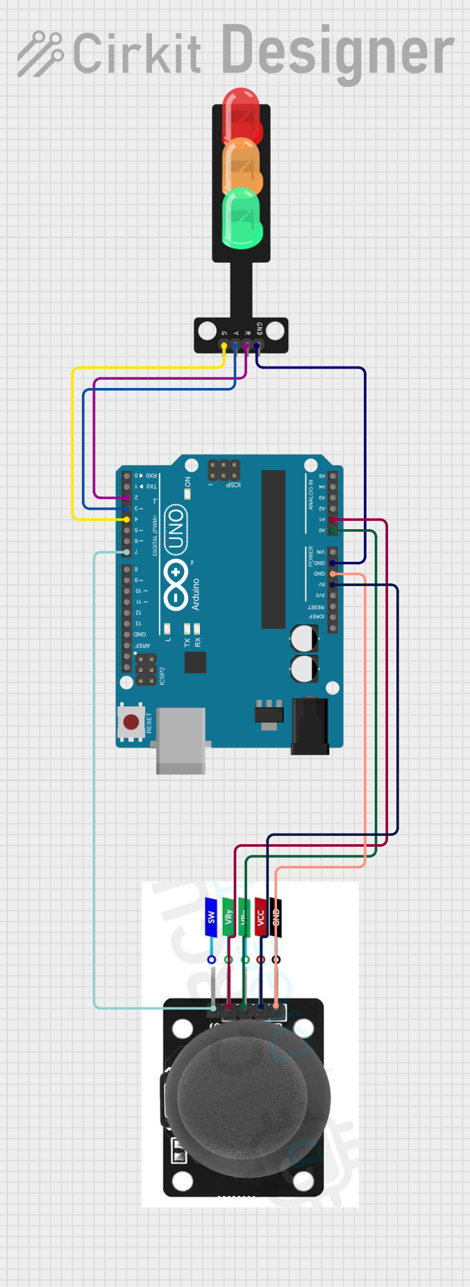
The circuit described herein is designed to control a traffic light system using an Arduino UNO microcontroller and a joystick module. The system allows a user to manipulate the traffic light by moving the joystick in different directions. Each direction corresponds to a different state of the traffic light:
- Moving the joystick up turns on the red light.
- Moving the joystick left turns on the yellow light.
- Moving the joystick right turns on the green light.
- Moving the joystick down turns on all lights.
The circuit is powered by the 5V output from the Arduino UNO, which also provides ground connections to the other components. Analog inputs from the joystick module are read to determine the position of the joystick, and digital outputs from the Arduino control the individual lights of the traffic light module.
Component List
Arduino UNO
- Description: A microcontroller board based on the ATmega328P.
- Purpose: Acts as the central processing unit for the circuit, reading joystick inputs and controlling the traffic light outputs.
Traffic Light
- Description: A module with three LEDs (Red, Yellow, Green) representing a traffic light.
- Purpose: Displays the traffic light status based on the joystick input.
Joystick Module
- Description: An input device with two analog axes (VRX, VRY) and a pushbutton switch (SW).
- Purpose: Provides user input to control the traffic light system.
Wiring Details
Arduino UNO
- 5V: Provides power to the Joystick module.
- GND: Common ground for the Joystick module and Traffic Light.
- A0: Reads the X-axis (VRX) of the Joystick module.
- A1: Reads the Y-axis (VRY) of the Joystick module.
- D2: Controls the Red LED of the Traffic Light.
- D3: Controls the Yellow LED of the Traffic Light.
- D4: Controls the Green LED of the Traffic Light.
Traffic Light
- Green: Connected to Arduino UNO pin D4.
- Yellow: Connected to Arduino UNO pin D3.
- Red: Connected to Arduino UNO pin D2.
- GND: Shared ground with Arduino UNO.
Joystick Module
- SW: Not used in this circuit.
- VRY: Connected to Arduino UNO pin A1.
- VRX: Connected to Arduino UNO pin A0.
- VCC: Powered by Arduino UNO 5V.
- GND: Shared ground with Arduino UNO.
Documented Code
/*
 * This Arduino sketch controls a traffic light system using a joystick module.
 * When the joystick is moved up, the red LED turns on.
 * When the joystick is moved left, the yellow LED turns on.
 * When the joystick is moved right, the green LED turns on.
 * When the joystick is moved down, all LEDs turn on.
 */

const int redLedPin = 2;
const int yellowLedPin = 3;
const int greenLedPin = 4;
const int joystickXPin = A0;
const int joystickYPin = A1;

void setup() {
  pinMode(redLedPin, OUTPUT);
  pinMode(yellowLedPin, OUTPUT);
  pinMode(greenLedPin, OUTPUT);
  pinMode(joystickXPin, INPUT);
  pinMode(joystickYPin, INPUT);
}

void loop() {
  int xValue = analogRead(joystickXPin);
  int yValue = analogRead(joystickYPin);

  if (yValue < 300) { // Joystick moved up
    digitalWrite(redLedPin, HIGH);
    digitalWrite(yellowLedPin, LOW);
    digitalWrite(greenLedPin, LOW);
  } else if (xValue < 300) { // Joystick moved left
    digitalWrite(redLedPin, LOW);
    digitalWrite(yellowLedPin, HIGH);
    digitalWrite(greenLedPin, LOW);
  } else if (xValue > 700) { // Joystick moved right
    digitalWrite(redLedPin, LOW);
    digitalWrite(yellowLedPin, LOW);
    digitalWrite(greenLedPin, HIGH);
  } else if (yValue > 700) { // Joystick moved down
    digitalWrite(redLedPin, HIGH);
    digitalWrite(yellowLedPin, HIGH);
    digitalWrite(greenLedPin, HIGH);
  } else { // Joystick in neutral position
    digitalWrite(redLedPin, LOW);
    digitalWrite(yellowLedPin, LOW);
    digitalWrite(greenLedPin, LOW);
  }
  delay(100); // Small delay to avoid flickering
}
This code is saved as sketch.ino and should be uploaded to the Arduino UNO microcontroller to operate the traffic light system as intended.