
Arduino UNO-Based Smart Lock System with Keypad and Servo Motor
View and Edit Project In Cirkit Designer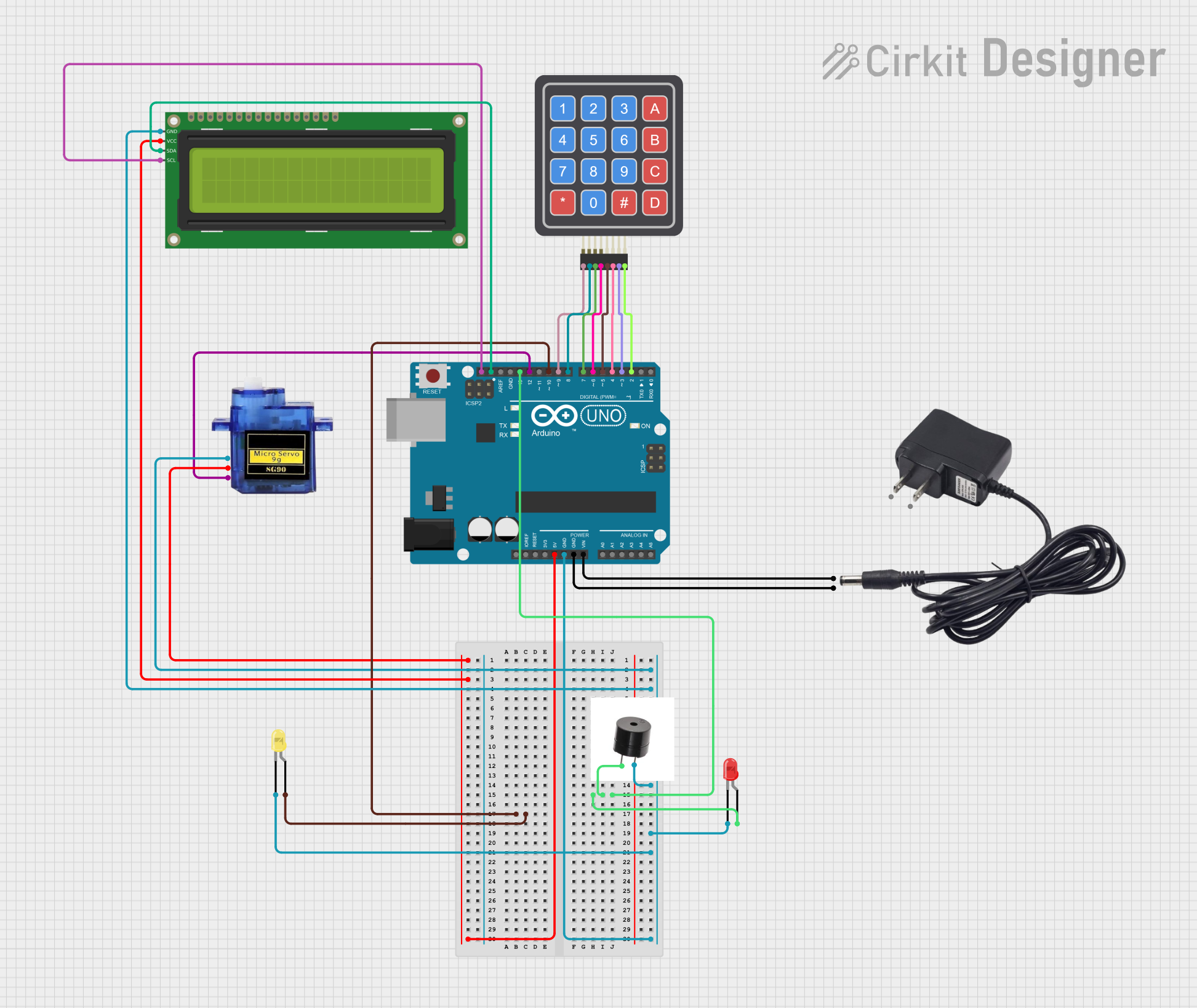
Circuit Documentation
Summary
This circuit is designed to control a door lock mechanism using a keypad, an LCD display, and a servo motor. The system is powered by a 12V adapter and is controlled by an Arduino UNO microcontroller. The circuit also includes LEDs and a buzzer for visual and auditory feedback.
Component List
Arduino UNO
- Description: A microcontroller board based on the ATmega328P.
- Pins: UNUSED, IOREF, Reset, 3.3V, 5V, GND, Vin, A0, A1, A2, A3, A4, A5, SCL, SDA, AREF, D13, D12, D11, D10, D9, D8, D7, D6, D5, D4, D3, D2, D1, D0
LED: Two Pin (yellow)
- Description: A yellow LED with two pins.
- Pins: cathode, anode
Buzzer
- Description: A simple buzzer for sound output.
- Pins: +, GND
4x4 Keypad (Simulator)
- Description: A 4x4 matrix keypad for user input.
- Pins: R1, C4, R2, C2, R3, R4, C1, C3
16x2 I2C LCD
- Description: A 16x2 character LCD with I2C interface.
- Pins: GND, VCC, SDA, SCL
Micro servo 9G
- Description: A small servo motor for mechanical movement.
- Pins: GND, +5V, PWM
12v Adapter
- Description: A 12V power adapter.
- Pins: VCC, GND
LED: Two Pin (red)
- Description: A red LED with two pins.
- Pins: cathode, anode
Wiring Details
Arduino UNO
- 5V: Connected to VCC of Micro servo 9G and 16x2 I2C LCD.
- GND: Connected to GND of Micro servo 9G, 16x2 I2C LCD, buzzer, red LED, yellow LED, and 12v Adapter.
- Vin: Connected to VCC of 12v Adapter.
- D13: Connected to anode of red LED and + of buzzer.
- D10: Connected to anode of yellow LED.
- D12: Connected to PWM of Micro servo 9G.
- SCL: Connected to SCL of 16x2 I2C LCD.
- SDA: Connected to SDA of 16x2 I2C LCD.
- D9: Connected to R1 of 4x4 Keypad.
- D8: Connected to R2 of 4x4 Keypad.
- D7: Connected to R3 of 4x4 Keypad.
- D6: Connected to R4 of 4x4 Keypad.
- D5: Connected to C1 of 4x4 Keypad.
- D4: Connected to C2 of 4x4 Keypad.
- D3: Connected to C3 of 4x4 Keypad.
- D2: Connected to C4 of 4x4 Keypad.
LED: Two Pin (yellow)
- anode: Connected to D10 of Arduino UNO.
- cathode: Connected to GND.
Buzzer
- +: Connected to D13 of Arduino UNO.
- GND: Connected to GND.
4x4 Keypad (Simulator)
- R1: Connected to D9 of Arduino UNO.
- R2: Connected to D8 of Arduino UNO.
- R3: Connected to D7 of Arduino UNO.
- R4: Connected to D6 of Arduino UNO.
- C1: Connected to D5 of Arduino UNO.
- C2: Connected to D4 of Arduino UNO.
- C3: Connected to D3 of Arduino UNO.
- C4: Connected to D2 of Arduino UNO.
16x2 I2C LCD
- GND: Connected to GND.
- VCC: Connected to 5V.
- SDA: Connected to SDA of Arduino UNO.
- SCL: Connected to SCL of Arduino UNO.
Micro servo 9G
- GND: Connected to GND.
- +5V: Connected to 5V.
- PWM: Connected to D12 of Arduino UNO.
12v Adapter
- VCC: Connected to Vin of Arduino UNO.
- GND: Connected to GND.
LED: Two Pin (red)
- anode: Connected to D13 of Arduino UNO.
- cathode: Connected to GND.
Code Documentation
#include <LiquidCrystal_I2C.h>
#include <Keypad.h>
#include <Servo.h>
#include <Wire.h>

#define ROW_NUM 4
#define COLUMN_NUM 4
#define SERVO_PIN 12

LiquidCrystal_I2C lcd(0x27, 16, 2); // Update address if needed
Servo servo;

char keys[ROW_NUM][COLUMN_NUM] = {
  {'1', '2', '3', 'A'},
  {'4', '5', '6', 'B'},
  {'7', '8', '9', 'C'},
  {'*', '0', '#', 'D'}
};

byte pin_rows[ROW_NUM] = {9, 8, 7, 6}; // Connect to the row pinouts of the keypad
byte pin_column[COLUMN_NUM] = {5, 4, 3, 2}; // Connect to the column pinouts of the keypad

Keypad keypad = Keypad(makeKeymap(keys), pin_rows, pin_column, ROW_NUM, COLUMN_NUM);

const String password_1 = "71022";
const String password_2 = "2025A";
const String password_3 = "123ABC";
String input_password;
int angle = 0;
unsigned long lastTime = 0;

void setup() {
  Serial.begin(9600);
  lcd.init();
  lcd.backlight();
  lcd.clear();
  input_password.reserve(32);
  pinMode(10, OUTPUT);
  pinMode(13, OUTPUT);
  servo.attach(SERVO_PIN);
  servo.write(0);
  lastTime = millis();
}

void loop() {
  char key = keypad.getKey();
  if (key) {
    Serial.println(key);
    lcd.setCursor(0,0);
    lcd.print(key);
    if (key == '*') {
      input_password = "";
    } else if (key == '#') {
      lcd.clear();
      if (input_password == password_1 || input_password == password_2 || input_password == password_3) {
        Serial.println("The password is correct, rotating Servo Motor to 90°");
        lcd.print("door open");
        angle = 90;
        servo.write(angle);
        digitalWrite(13, 0);
        digitalWrite(10, 1);
        delay(5000);
        lcd.clear();
        digitalWrite(10,0);
      } else {
        Serial.println("The password is incorrect, try again");
        lcd.print("Access Denied");
        digitalWrite(13, 1);
        delay(2000);
        digitalWrite(13,0);
        lcd.clear();
        lastTime = millis();
      }
      input_password = "";
    } else {
      input_password += key;
    }
  }
  if (angle == 90 && (millis() - lastTime) > 5000) {
    angle = 0;
    servo.write(angle);
    Serial.println("Rotating Servo Motor to 0°");
    lcd.clear();
    lcd.print("door is closed");
    delay(2000);
    lcd.clear();
  }
}
This code initializes the LCD, keypad, and servo motor. It reads input from the keypad and checks it against predefined passwords. If the password is correct, the servo motor rotates to 90 degrees, simulating the opening of a door. If the password is incorrect, an "Access Denied" message is displayed. The servo motor returns to 0 degrees after 5 seconds.